1. Product Overview
The ANENG MH11 Digital Megohmmeter is an insulation series digital tester designed for precise resistance measurements. It utilizes a low-loss, high-ratio inductance energy storage DC voltage converter to transform 12V DC into selectable output voltages of 250V, 500V, or 1000V DC. This instrument is suitable for testing insulation resistance in various applications, including motors, cables, mechanical and electrical equipment, telecommunications equipment, and power facilities.
It features a digital LCR Bridge for accurate resistance measurement, a wide measuring range, a backlight display for visibility in various conditions, a test lock function for continuous measurement, and an auto-power-off feature to conserve battery life. Its robust design allows for two-handed operation, and it includes a durable protective case.
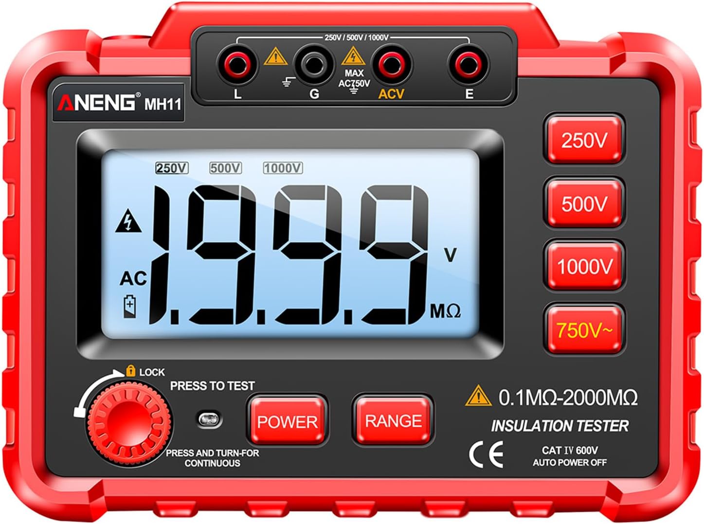
Figure 1.1: Front view of the ANENG MH11 Digital Megohmmeter, showing the large LCD display, function buttons, and input terminals.
2. Key Features
- Voltage Conversion: Converts 12V DC to 250V, 500V, or 1000V DC for insulation testing.
- Wide Application: Ideal for motors, cables, electrical equipment, telecommunications, and power facilities.
- Measurement Technology: Utilizes a digital LCR Bridge for precise resistance and insulation resistance measurements.
- User-Friendly Design: Features a backlight display, test lock for continuous operation, and automatic power-off.
- Power Supply: Operates on 8 AA LR6 (1.5V) batteries (not included), with a low voltage indication.
- Durable Construction: Equipped with an all-round protection and anti-drop cover made of silicone material to protect hardware from damage.

Figure 2.1: The ANENG MH11 Megohmmeter encased in its durable, anti-drop silicone protective cover, designed to safeguard the instrument from impacts.
3. Components and Controls
Familiarize yourself with the various parts and controls of the ANENG MH11 Megohmmeter for proper operation.

Figure 3.1: Labeled diagram of the ANENG MH11 Megohmmeter's components and controls.
- E terminal: High voltage output test terminal.
- AC voltage measurement positive input terminal.
- G: Protection end jack. When the measured object requires it, the guard ring eliminates leakage effect, and the guard ring electrode wire connects to the "G" terminal jack.
- L terminal: High voltage output test terminal.
- Power adapter jack: DC12V input.
- LCD display: Displays measurement data and unit symbols.
- Power switch: Self-locking power switch.
- High voltage measurement resistance indicator light: Illuminates during high voltage measurement.
- Test button.
- RANGE: Resistance range selection switch.
- 250V power switch.
- 500V power switch.
- 1000V power switch.
- AC750V AC voltage measurement switch.
4. Setup
4.1 Battery Installation
The ANENG MH11 requires 8 AA LR6 (1.5V) batteries for operation. Ensure the batteries are inserted with correct polarity.
- Locate the battery compartment on the back of the device.
- Open the battery compartment cover.
- Insert 8 AA LR6 (1.5V) batteries, observing the polarity markings (+/-).
- Close the battery compartment cover securely.
The device will indicate low voltage on the display when the batteries need replacement.
4.2 Test Lead Connection
Properly connect the test leads to the meter and the object under test.

Figure 4.1: Illustration of the test lead installation process. The probe tip is inserted into the lead connector.
- Connect the red test lead to the 'L' (High Voltage Output) terminal and the black test lead to the 'E' (Ground) terminal for insulation resistance measurements.
- For AC voltage measurement, connect the leads to the 'ACV' terminals.
- Ensure all connections are firm and secure before proceeding with any tests.
5. Operating Instructions
5.1 Powering On/Off
- To power on the device, press the POWER button (7).
- To power off, press the POWER button again. The device also features an auto-power-off function after 15 minutes of inactivity.
5.2 Insulation Resistance Measurement
- Ensure the device is powered on.
- Select the desired test voltage (250V, 500V, or 1000V) by pressing the corresponding voltage button (11, 12, or 13).
- Connect the test leads to the object whose insulation resistance you wish to measure.
- Press and hold the TEST button (9) to initiate the measurement. The high voltage measurement resistance indicator light (8) will illuminate.
- The insulation resistance value will be displayed on the LCD (6).
- For continuous measurement, press and turn the LOCK knob (9) to the continuous position.
- Release the TEST button or turn the LOCK knob back to stop the measurement.
5.3 AC Voltage Measurement
- Ensure the device is powered on.
- Press the AC750V switch (14).
- Connect the test leads to the AC voltage source.
- The AC voltage value will be displayed on the LCD (6).
6. Maintenance
- Cleaning: Use a soft, dry cloth to clean the exterior of the meter. Do not use abrasive cleaners or solvents.
- Storage: When not in use for extended periods, remove the batteries to prevent leakage. Store the meter in a cool, dry place, away from direct sunlight and extreme temperatures.
- Battery Replacement: Replace batteries promptly when the low voltage indicator appears to ensure accurate measurements.
- Test Leads: Inspect test leads regularly for any signs of damage, such as cracks or frayed insulation. Replace damaged leads immediately.
7. Troubleshooting
This section provides solutions to common issues you might encounter with your ANENG MH11 Megohmmeter.
| Problem | Possible Cause | Solution |
|---|---|---|
| Device does not power on. | Dead or incorrectly installed batteries. | Check battery polarity; replace with new AA LR6 batteries. |
| Low voltage indication. | Batteries are low. | Replace all 8 AA LR6 batteries. |
| Inaccurate or no reading during insulation test. | Loose test lead connection; short circuit in object; open circuit in object. | Ensure leads are securely connected. Refer to Figure 7.1 for short circuit vs. normal instrument readings. |
| Display shows "1" (Over Indication). | Measurement exceeds the upper limit of the selected range. | This indicates a very high resistance, often an open circuit or normal insulation. |

Figure 7.1: Comparison of display readings for a short circuit condition versus a normal instrument reading. A value less than 0.5 MΩ indicates a short circuit, while '1' indicates infinite resistance (normal insulation).
8. Specifications
Detailed technical specifications for the ANENG MH11 Digital Megohmmeter.

Figure 8.1: Official Technical Data Sheet for the ANENG MH11 Megohmmeter, detailing basic functions, measuring ranges, and accuracy.
| Parameter | Value |
|---|---|
| Output Voltage | 250V / 500V / 1000V |
| Short Circuit Current | <1.6mA |
| Median Resistance | 250V/500V: 2 MΩ, 1000V: 5 MΩ |
| Insulation Resistance Range | 0.1 MΩ - 2000 MΩ (varies by voltage) |
| Display | 90 x 48mm LCD, max display "1999" |
| Over Indication | Only highest digit shows "1" |
| Measurement Method | Double integral type A/D conversion |
| Sampling Rate | About 3 times/second |
| Power Consumption (empty load) | <300mW |
| Operating Environment | 0℃ - 40℃, humidity 30% RH - 85% RH |
| Power Supply | 8 x AA LR6 (1.5V) batteries (not included) |
| Automatic Shutdown | After 15 minutes of inactivity |
| Item Size | 165 x 120 x 57 mm / 6.5 x 4.72 x 2.25 inches |
| Item Weight | 1.6 pounds |
9. Safety Information
Please read and understand all safety warnings and operating instructions before using this instrument. Failure to do so could result in injury or damage to the meter or equipment under test.
- Do not use the meter if it appears damaged or if the test leads are damaged.
- Do not operate the meter in explosive gas, vapor, or dust environments.
- Always ensure the correct function and range are selected before making measurements.
- Be cautious when working with high voltages. Always assume circuits are live until proven otherwise.
- Do not exceed the maximum input values for any range.
- Keep hands and fingers behind the probe barriers during testing.
- Ensure the object under test is de-energized and discharged before connecting the meter for insulation resistance tests, unless performing a live insulation test under controlled conditions by qualified personnel.
- This device is not a toy. Keep out of reach of children.
10. Warranty and Support
Specific warranty information for this product is not provided in the available data. For warranty claims or technical support, please contact the seller or manufacturer directly through your purchase platform.
Please retain your purchase receipt as proof of purchase for any warranty or support inquiries.