1. Introduction
Thank you for choosing the HUTIANSN MicroZone MC6C Mini V2 2.4G 6CH Controller Transmitter. This radio system is designed for reliable control of various RC models, including fixed-wing aircraft, drones, multirotors, helicopters, and boats. This manual provides essential information for the proper setup, operation, and maintenance of your transmitter to ensure safe and enjoyable use.
Please read this manual thoroughly before operating the transmitter. Keep it for future reference.
Safety Precautions
- Always ensure batteries are correctly installed and fully charged before use.
- Operate your RC model in open areas, away from people, vehicles, and obstacles.
- Never operate the transmitter in adverse weather conditions (rain, strong winds).
- Always turn on the transmitter first, then the receiver. When finished, turn off the receiver first, then the transmitter.
- Keep the transmitter away from moisture, dust, and direct sunlight.
2. Product Overview
The MicroZone MC6C Mini V2 is a 6-channel 2.4GHz radio control system. Familiarize yourself with the various components and controls of the transmitter.
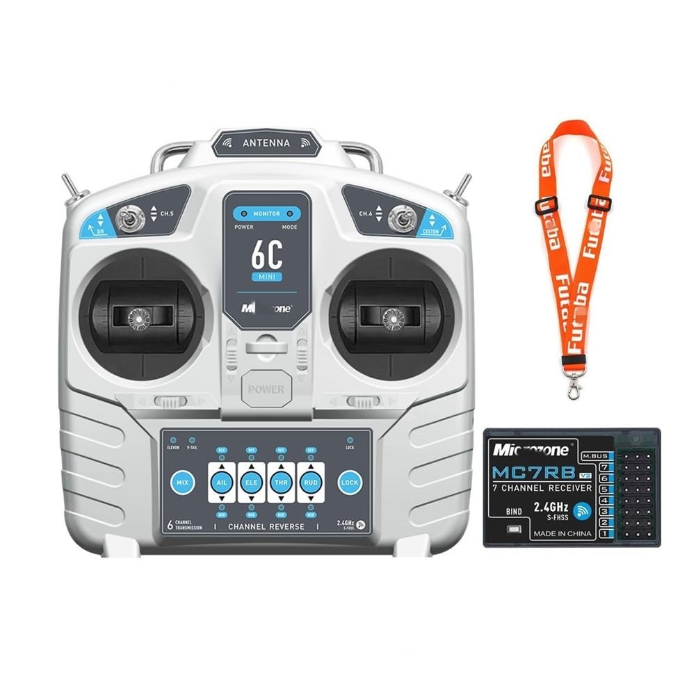
Figure 2.1: Front view of the HUTIANSN MicroZone MC6C Mini V2 Transmitter. This image displays the overall design and layout of the control sticks and switches.

Figure 2.2: Back view of the HUTIANSN MicroZone MC6C Mini V2 Transmitter. This image shows the battery compartment and handle.
Transmitter Components

Figure 2.3: Detailed diagram of the MicroZone MC6C Mini V2 Transmitter controls and indicators. This diagram labels the power switch, mode light, D/R switch, channel switches, rockers, trim levers, built-in antenna, and the channel reverse panel with its indicators and lock switch.
- Power Switch: Turns the transmitter on/off.
- Mode Light: Indicates the current operating mode or status.
- D/R Switch: Dual Rate switch for adjusting control sensitivity.
- Channel 5 & 6 Switches: Auxiliary channel switches for various functions.
- Rocker Sticks: Primary control inputs for throttle, elevator, rudder, and aileron.
- Trim Levers: Fine-tune the neutral position of control surfaces (Throttle Trim, Elevator Trim, Rudder Trim, Aileron Trim).
- Built-in Antenna: 2.4GHz signal transmission.
- Channel Reverse Panel: Allows reversing the direction of individual channels (AIL, ELE, THR, RUD).
- Lock Indicator & Switch: Indicates and controls the locking mechanism for channel settings.
- Mixed Control Indicators: V Tail Mixed Control, Delta Wing Mixed Control, Hybrid Control Function.
3. Setup
3.1 Battery Installation
The transmitter requires four (4) 1.5V AA batteries for operation. Rechargeable batteries can also be used.
- Locate the battery compartment on the back of the transmitter (refer to Figure 2.2).
- Open the battery compartment cover.
- Insert four AA batteries, ensuring correct polarity (+ and -) as indicated inside the compartment.
- Close the battery compartment cover securely.
Note: The transmitter features a low voltage alarm (LED indicator and buzzer) to alert you when battery power is low. Replace or recharge batteries promptly.
3.2 Receiver Binding (Pairing)
To establish communication between the transmitter and receiver, a binding process is required. Refer to your receiver's specific instructions for its binding procedure, as it may vary. Generally, the steps involve:
- Ensure the transmitter is turned off.
- Place the receiver in binding mode (usually by connecting a bind plug or pressing a bind button while powering on).
- Power on the receiver. The receiver's LED should indicate it's in binding mode.
- While holding the bind button on the transmitter (if applicable, or following its specific bind sequence), turn on the transmitter.
- Observe the LEDs on both the transmitter and receiver. A solid light typically indicates successful binding.
- Turn off both the receiver and transmitter, then power them on normally (transmitter first, then receiver) to confirm the bind.
3.3 Initial Checks
- After binding, test all control surfaces and functions on your model without the propeller or in a safe environment.
- Verify that all controls respond correctly to transmitter inputs (e.g., moving the throttle stick increases motor speed, moving the aileron stick moves ailerons).
- Check the range of your radio system in a safe, open area before actual flight or operation.
4. Operation
This section details the functions of the transmitter's controls. Refer to Figure 2.3 for component locations.
4.1 Basic Controls (Rocker Sticks)
- Throttle: Controls motor speed/power. (Typically left stick, vertical movement for Mode 2).
- Elevator: Controls pitch (nose up/down). (Typically right stick, vertical movement for Mode 2).
- Rudder: Controls yaw (nose left/right). (Typically left stick, horizontal movement for Mode 2).
- Aileron: Controls roll (wing tip up/down). (Typically right stick, horizontal movement for Mode 2).
4.2 Trim Levers
Trim levers are used to make small adjustments to the neutral position of your model's control surfaces. If your model drifts without stick input, use the corresponding trim lever to correct it.
- Throttle Trim: Adjusts the idle speed or neutral throttle position.
- Elevator Trim: Adjusts the neutral elevator position.
- Rudder Trim: Adjusts the neutral rudder position.
- Aileron Trim: Adjusts the neutral aileron position.
4.3 D/R (Dual Rate) Switch
The D/R switch allows you to change the sensitivity of the control sticks. This is useful for adjusting between precise control (low rate) and aggressive maneuvers (high rate).
4.4 Channel 5 & 6 Switches
These switches provide control for auxiliary channels (channels 5 and 6). They can be assigned to control various functions on your model, such as landing gear, flaps, lights, or other accessories, depending on your receiver and model setup.
4.5 Channel Reverse
The channel reverse function allows you to change the direction of a control channel's response. If a control surface moves in the opposite direction to your stick input, use the corresponding reverse switch on the channel reverse panel (refer to Figure 2.3) to correct it.
- AIL (Aileron) Reverse: Reverses aileron control direction.
- ELE (Elevator) Reverse: Reverses elevator control direction.
- THR (Throttle) Reverse: Reverses throttle control direction.
- RUD (Rudder) Reverse: Reverses rudder control direction.
Important: Always verify control directions after making any changes to channel reverse settings.
4.6 Mixed Control Functions
The transmitter supports various mixed control functions, indicated on the channel reverse panel (refer to Figure 2.3). These are advanced settings for specific model types:
- V Tail Mixed Control: For models with V-tail configurations, where elevator and rudder functions are combined.
- Delta Wing Mixed Control: For delta wing or elevon aircraft, where elevator and aileron functions are combined.
- Hybrid Control Function Switch: Activates or deactivates hybrid mixing modes.
Consult your model's manual for specific mixing requirements and how to activate these functions on the transmitter.
5. Maintenance
5.1 Cleaning
- Wipe the transmitter's exterior with a soft, dry cloth.
- Do not use solvents, alcohol, or abrasive cleaners, as these can damage the plastic casing.
- Keep the rocker sticks and switches free from dust and debris.
5.2 Storage
- Store the transmitter in a cool, dry place, away from direct sunlight and extreme temperatures.
- If storing for an extended period, remove the AA batteries to prevent leakage and damage.
5.3 Battery Care
- Always use fresh, high-quality AA batteries.
- If using rechargeable AA batteries, ensure they are fully charged before each use.
- Do not mix old and new batteries, or different types of batteries.
- Dispose of used batteries responsibly according to local regulations.
6. Troubleshooting
| Problem | Possible Cause | Solution |
|---|---|---|
| Transmitter does not power on. | Dead or incorrectly installed batteries. | Check battery polarity. Replace with fresh batteries. |
| No control response from model. | Not bound to receiver, receiver not powered, or out of range. | Perform binding procedure. Ensure receiver is powered. Check range. |
| Control surface moves in wrong direction. | Channel reverse setting is incorrect. | Adjust the corresponding channel reverse switch on the transmitter. |
| Model drifts without stick input. | Trims are not centered or correctly adjusted. | Adjust the trim levers for the affected control. |
| Low voltage alarm sounds. | Transmitter batteries are low. | Replace or recharge the AA batteries immediately. |
7. Specifications
| Brand | HUTIANSN |
| Model Name | MicroZone MC6C Mini V2 |
| Number of Channels | 6 |
| Applicable Models | Fixed-wing model aircraft, unmanned aerial vehicles, vehicles, ships |
| RF Range | 2401MHZ - 2479MHZ |
| RF Power | Less than 100MW |
| Working Current | Less than 120MA |
| Working Voltage | 4.5V - 8.5V |
| Modulation Mode | FSK |
| Sensitivity | 1024 |
| Signal Output | 6-way PWM signal and 1-way SBUS signal |
| Analog & External Power Supply | Yes (no more than 8V) |
| Low Voltage Alarm | LED indicator and buzzer alarm simultaneously |
| Power Supply | 6V (4 x 1.5V AA batteries) |
| Certification Standards | FCC, CE_RED (conforming to European standards) |
| Material Type | Plastic |
| Country of Origin | China |
8. Warranty and Support
HUTIANSN products are manufactured to high-quality standards. For specific warranty information, please refer to the documentation provided with your purchase or contact your retailer. Keep your proof of purchase for any warranty claims.
For technical support or inquiries, please contact the retailer or manufacturer directly. Contact information can typically be found on the product packaging or the retailer's website.