1. Introduction
This manual provides detailed instructions for the installation, operation, and maintenance of your Generic N1996 L-A690 T5900V E2589 AM2 DDR2 Desktop Motherboard. Please read this manual thoroughly before proceeding with installation to ensure proper setup and to prevent damage to the product or other components. Keep this manual for future reference.
2. Product Overview
The Generic N1996 L-A690 T5900V E2589 AM2 DDR2 Desktop Motherboard is designed to provide a stable and reliable foundation for your desktop computer system. It supports AM2 socket processors and DDR2 memory, making it suitable for various computing needs.

Figure 2.1: Overall top-down view of the motherboard, showing the CPU socket, RAM slots, and various expansion slots and connectors.
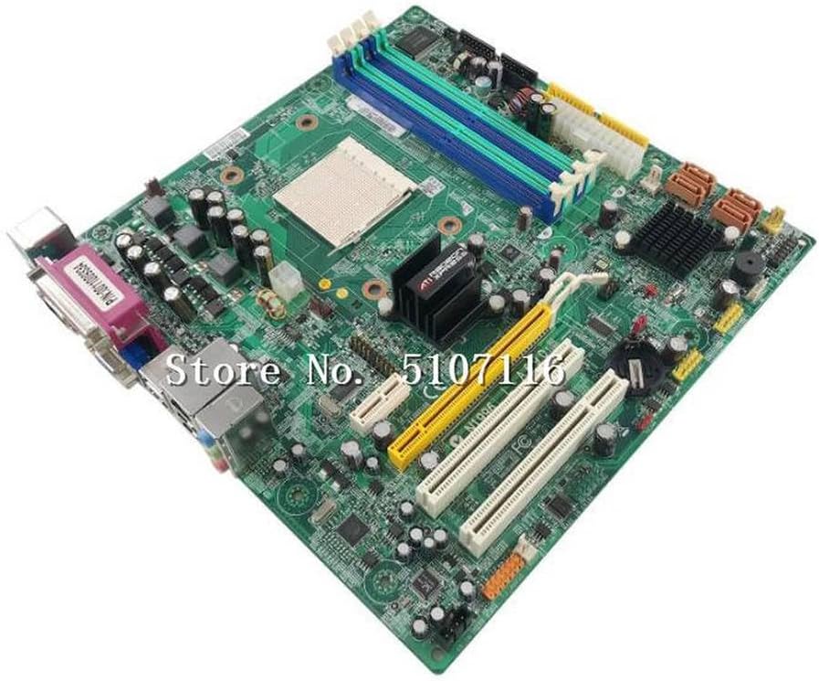
Figure 2.2: Angled view highlighting the CPU socket, four DDR2 RAM slots (two blue, two green), and multiple PCI/PCIe expansion slots.

Figure 2.3: Detailed view of the rear input/output (I/O) panel, featuring PS/2 ports, a serial port, a VGA port, USB ports, an Ethernet port, and audio jacks.
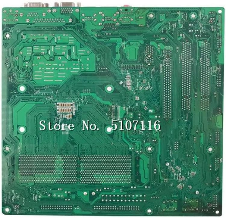
Figure 2.4: View of the motherboard's backside, showing solder points and circuit traces.
3. Setup and Installation
Before beginning installation, ensure you have a clean, static-free workspace. Always handle the motherboard by its edges to avoid touching components or connectors. It is recommended to wear an anti-static wrist strap.
3.1. Safety Precautions
- Disconnect power from your computer before installing or removing any components.
- Ground yourself to prevent electrostatic discharge (ESD) damage.
- Refer to your computer case manual for specific mounting instructions.
3.2. Motherboard Installation
- Prepare the Case: Install the I/O shield into the rear opening of your computer case.
- Mount the Motherboard: Carefully align the motherboard with the standoffs in your case. Secure it with screws, ensuring not to overtighten.
- Install CPU: Open the CPU socket lever, align the CPU with the socket (matching the golden triangle/arrow), gently place it in, and close the lever.
- Install CPU Cooler: Attach the CPU cooler according to its manufacturer's instructions.
- Install RAM: Open the clips on the DDR2 memory slots. Align the memory modules with the key notch and press firmly until the clips snap into place.
- Connect Power: Connect the 24-pin ATX power connector and the 4-pin ATX 12V power connector from your power supply to the motherboard.
- Connect Storage Devices: Connect SATA or IDE cables from your storage drives (HDD/SSD/Optical Drive) to the corresponding ports on the motherboard.
- Connect Front Panel Cables: Connect the power switch, reset switch, HDD LED, power LED, and front USB/audio headers from your case to the motherboard. Refer to the motherboard's silkscreen labels for correct pin assignments.
- Install Expansion Cards: Insert any necessary PCI or PCIe expansion cards (e.g., graphics card, sound card) into their respective slots and secure them.
4. Operating Instructions
After successful installation, you can power on your system.
4.1. Initial Boot and BIOS/UEFI Setup
- Power On: Press the power button on your computer case.
- Access BIOS/UEFI: During the initial boot sequence, repeatedly press the designated key (commonly DEL, F2, F10, or F12) to enter the BIOS/UEFI setup utility.
- Configure Settings: In the BIOS/UEFI, you can configure boot order, system time, and other hardware settings. Save changes and exit to continue booting.
- Operating System Installation: Insert your operating system installation media (USB drive or DVD) and follow the on-screen prompts to install the OS.
- Driver Installation: After OS installation, install all necessary drivers for the motherboard chipset, audio, network, and any other integrated components. These are typically provided on a driver CD or available for download from the manufacturer's website.
5. Maintenance
Regular maintenance helps ensure the longevity and optimal performance of your motherboard and system.
- Dust Removal: Periodically clean dust from the motherboard and components using compressed air. Ensure the system is powered off and unplugged before cleaning.
- Check Connections: Occasionally verify that all cables and expansion cards are securely seated.
- BIOS/Firmware Updates: Check the manufacturer's website for BIOS/firmware updates. Only update if necessary and follow the instructions carefully to avoid system instability.
- Temperature Monitoring: Use system monitoring software to keep an eye on CPU and chipset temperatures to prevent overheating.
6. Troubleshooting
If you encounter issues, refer to the following common troubleshooting steps:
- No Power: Ensure all power cables (24-pin ATX, 4-pin ATX 12V) are securely connected to the motherboard and power supply. Check the power supply switch and wall outlet.
- No Display: Verify that the monitor is connected to the correct video output (integrated or discrete graphics card) and is powered on. Reseat the graphics card and RAM modules.
- POST Beep Codes: Listen for beep codes during startup. Consult the motherboard's specific beep code guide (if available) to diagnose the issue (e.g., RAM error, graphics card error).
- System Instability/Crashes: Check for overheating. Ensure all drivers are up to date. Test RAM modules individually.
- Component Not Detected: Reseat the component (e.g., hard drive, expansion card). Check cable connections. Verify BIOS/UEFI settings.
- Clear CMOS: If the system fails to boot after changing BIOS settings, clear the CMOS by removing the CMOS battery for a few minutes or using the designated clear CMOS jumper on the motherboard.
7. Specifications
The following table outlines the key specifications for the Generic N1996 L-A690 T5900V E2589 AM2 DDR2 Desktop Motherboard:
| Feature | Specification |
|---|---|
| Brand | Generic |
| Manufacturer | Generic |
| Model Name | N1996 L-A690 T5900V E2589 AM2 DDR2 |
| Manufacturer Reference | LHY_SERVS_12939 |
| ASIN | B0CXYXC83C |
| Date First Available | March 13, 2024 |
| Spare Parts Availability | Information not available |
| Guaranteed Software Updates Until | Information not available |
8. Warranty and Support
Based on the available product information, specific details regarding warranty coverage and direct technical support channels are not provided. For any issues or inquiries, please refer to your point of purchase or the general support resources for Generic products.