1. Introduction
This manual provides detailed instructions for the installation, operation, and maintenance of the GERRIT A2000C-F Electronic Governor Actuator and the C1000A Speed Controller. This system is designed to precisely control the speed of generator sets, ensuring stable and efficient performance. Please read this manual thoroughly before installation and operation to ensure correct usage and prevent damage.
The A2000C-F actuator is compatible with various engine models, including Weichai WC6170, WP12, WP13; Yuchai YC6MJ, YC6T, YC6C, YC6112; Jichai 12V190; Zichai ZC160; and Motionless WD327TAD.
2. Product Overview
The GERRIT A2000C-F is a compact, low-friction electromagnetic actuator designed for generator speed control. When paired with the C1000A speed controller, it forms a robust and reliable fuel control system for optimal engine performance and longevity.
2.1 Key Components
- A2000C-F Electromagnetic Actuator: Responsible for physically adjusting the fuel rack based on signals from the speed controller.
- C1000A Speed Controller: An electronic governor that processes engine speed signals and sends commands to the actuator to maintain desired RPM.
- Speed Sensor: Detects engine speed and provides feedback to the C1000A controller.
2.2 Product Features
- Small, low-cost, low-friction design.
- Rugged construction suitable for control cabinets or engine-mounted enclosures.
- Optimized for long-life fuel control system results.

Figure 1: Complete system showing the A2000C-F Actuator, C1000A Speed Controller, and a speed sensor.
3. Specifications
| Feature | Specification |
|---|---|
| Actuator Model | A2000C-F |
| Controller Model | C1000A |
| Compatible Engine Models | Weichai WC6170, WP12, WP13; Yuchai YC6MJ, YC6T, YC6C, YC6112; Jichai 12V190; Zichai ZC160; Motionless WD327TAD |
| Actuator Mounting Dimensions | 75mm x 75mm (mounting base) |
| Speed Sensor Thread | M18*1.5 |
| Speed Sensor Length | 70mm |
| Speed Sensor Diameter | 18mm |
| Item Weight | Approximately 1.76 pounds (0.8 kg) |
| Package Dimensions | 1.18 x 0.79 x 0.39 inches (30 x 20 x 10 mm) (Note: This likely refers to a small component's packaging.) |

Figure 2: Actuator mounting base dimensions.

Figure 3: Speed sensor dimensions.
4. Setup and Installation
Proper installation is critical for the safe and effective operation of the A2000C-F actuator and C1000A controller. It is recommended that installation be performed by qualified personnel.
4.1 Pre-Installation Checks
- Ensure the engine is completely shut down and secured against accidental startup.
- Verify that the mobility of the fuel pump rack is free and not stuck. The rack must be able to move freely to the stop-oil position.
- Confirm compatibility of the actuator with your specific engine model.
- Inspect all components for any visible damage before installation.
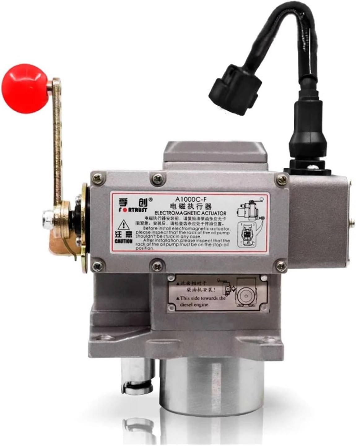
Figure 4: Actuator with important installation notes. Ensure fuel pump rack mobility and correct orientation towards the diesel engine.
4.2 Actuator Mounting
- Mount the A2000C-F actuator securely to the engine or generator set using appropriate fasteners. Refer to Figure 2 for mounting base dimensions (75mm x 75mm).
- Ensure the actuator is oriented correctly, with the designated side facing towards the diesel engine as indicated on the product label (see Figure 4).
- Connect the actuator linkage to the engine's fuel pump rack. Ensure smooth, unrestricted movement throughout the full range of motion.
4.3 Speed Sensor Installation
- Install the speed sensor into the designated port on the engine. The sensor has an M18*1.5 thread (see Figure 3).
- Adjust the sensor gap according to engine manufacturer specifications to ensure accurate speed detection.
4.4 Wiring Connections
Connect the A2000C-F actuator, C1000A speed controller, and speed sensor according to the wiring diagram provided with your specific engine or generator set. Ensure all connections are secure and properly insulated to prevent short circuits or electrical interference.
- Connect the actuator's electrical connector to the C1000A controller.
- Connect the speed sensor to the C1000A controller's input terminals.
- Provide appropriate power supply (typically 12V or 24V DC) to the C1000A controller.
5. Operating Instructions
Once installed and wired, the C1000A speed controller allows for fine-tuning of engine speed and stability. The controller typically features several adjustment potentiometers.
Figure 5: C1000A Speed Controller with adjustment points.
5.1 Initial Startup and Adjustment
- Start the Engine: Carefully start the engine and allow it to reach operating temperature.
- Idle Speed Adjustment: Use the "IDLE" potentiometer on the C1000A controller to set the desired engine idle speed.
- Rated Speed Adjustment: Adjust the "RATED SPEED" potentiometer to achieve the desired operating speed under load.
- Stability Adjustment: The "STABILITY" control fine-tunes the response to speed changes, preventing oscillations. Adjust for smooth engine operation.
- Gain Adjustment: "GAIN" controls the sensitivity of the governor. Higher gain means a faster response but can lead to instability if set too high. Adjust for optimal balance between response and stability.
- Droop Adjustment: "DROOP" allows for a slight decrease in engine speed as load increases. This is often used for parallel operation of multiple generators. Adjust as required for your application.
- Max Fuel Adjustment: "MAX FUEL" limits the maximum fuel delivery, protecting the engine from over-fueling. Set this according to engine manufacturer specifications.
Note: Always make small adjustments and observe engine behavior. Refer to your engine's specific manual for recommended settings and procedures.
6. Maintenance
Regular maintenance ensures the longevity and reliable performance of your GERRIT A2000C-F actuator and C1000A speed controller system.
- Visual Inspection: Periodically inspect the actuator, controller, and wiring for any signs of wear, corrosion, or damage.
- Linkage Check: Ensure the actuator linkage to the fuel pump rack remains free of obstructions and moves smoothly. Lubricate if necessary, following engine manufacturer guidelines.
- Electrical Connections: Verify that all electrical connections are tight and free from corrosion.
- Cleaning: Keep the components clean and free from dust, dirt, and moisture.
7. Troubleshooting
This section provides guidance for common issues. For complex problems, consult a qualified technician.
| Problem | Possible Cause | Solution |
|---|---|---|
| Engine speed unstable/oscillating |
|
|
| Engine does not reach desired speed |
|
|
| No engine speed control |
|
|
8. Warranty and Support
For warranty information and technical support, please refer to the documentation provided at the time of purchase or contact your authorized GERRIT dealer. Keep your purchase receipt as proof of purchase.
For further assistance, please visit the official GERRIT website or contact customer service.