1. Introduction
This manual provides detailed instructions for the installation, operation, and maintenance of the GRYVOZE DTFM-IN1-AP Digital Turbine Fuel Flow Meter. This device is designed for accurate measurement of various liquids, including water, diesel, gas oil, gasoline, kerosene, methanol, and E15. Please read this manual thoroughly before use to ensure proper function and safety.

Image 1: GRYVOZE DTFM-IN1-AP Digital Turbine Fuel Flow Meter with included 3/4 inch adapters.
2. Safety Information
- Dry Environment Only: This device is not waterproof. It is suitable for sheltered locations. Keep away from rain, high humidity, and condensation. Do not immerse the meter in liquid.
- Liquid Compatibility: Ensure the liquid being measured is compatible with the meter's materials (aluminum alloy casing, stainless steel turbine). Not suitable for drinking water, alkaline water, or other corrosive liquids.
- Flow Direction: Always install the meter according to the indicated flow direction arrow on the device to ensure accurate readings and proper operation.
- PCB Circuit Board: The internal PCB circuit board is not waterproof. Avoid wetting it during battery replacement or any other maintenance.
3. Product Overview
The GRYVOZE DTFM-IN1-AP is a robust digital turbine flow meter designed for precise liquid measurement. It features an easy-to-read LCD display and durable construction.
3.1 Key Features
- High Accuracy: Provides precise readings with a ±1% accuracy.
- Clear LCD Display: Shows real-time flow rates, single accumulated totals, and total cumulative flow data.
- Five Unit Options: Easily switch between Gallons (GAL), Quarts (QTS), Pints (PTS), Liters (L), and cubic meters (m³).
- Energy-Efficient: Automatic display shut-off after 10 minutes of inactivity, with a standby time of over 1 year.
- Rugged Design: Constructed with an aluminum alloy casing and stainless steel turbine for durability.
- Non-Volatile Memory: Retains accumulated data even when power is off or batteries are replaced.

Image 2: Overview of the meter's display elements and how instantaneous and total cumulative flow are shown.

Image 3: Visual representation of the LCD monitor's key features.
4. Setup and Installation
4.1 Unpacking
Carefully remove all components from the packaging. Verify that all items listed in the 'What's in the Box' section are present and undamaged.
4.2 Battery Installation
The meter requires 2 x AAA LRO3 batteries. Access the battery compartment, typically located behind the display panel. Ensure correct polarity when inserting batteries.

Image 4: Internal view showing the PCB circuit board and battery placement (2 x AAA LRO3 batteries).
4.3 Mounting and Connection
- Determine Flow Direction: Identify the flow direction arrow on the meter's body. The meter must be installed so that liquid flows in the direction of this arrow.
- Thread Type: The meter uses NPT threads. Ensure your piping connections are compatible.
- Adapter Use: For 3/4 inch connections, attach the provided 3/4 inch adapters to the 1-inch NPT ports of the flow meter.
- Secure Connection: Connect the meter securely into your pipeline. Use appropriate sealing tape or compound to prevent leaks.
- Display Orientation: The display panel can be rotated 180 degrees by removing the screws, allowing for optimal viewing angle after installation.

Image 5: Important note regarding correct flow direction during installation.
4.4 Electromagnetic Interference
This flow meter is equipped with an anti-electromagnetic interference function, allowing it to be installed in close proximity to pumps or motors. This feature mitigates interference from magnetic fields generated by such equipment, which can otherwise cause inaccurate counting even without liquid flow.
5. Operation
5.1 Power On/Off
The display automatically turns on when liquid flows through the meter. It can also be activated by pressing any key. The display will automatically turn off after 10 minutes of inactivity to conserve energy.

Image 6: Illustration of the auto turn-off function and low battery indicator.
5.2 Display Modes
The meter can display instantaneous flow, single cumulative flow, and total cumulative flow. Use the 'DISPLAY' key to cycle through these modes.
5.3 Unit Setting
To change the measurement unit (GAL, QTS, PTS, L, m³):
- Simultaneously press and hold the 'CALIBRATE' (C) and 'DISPLAY' (D) keys for more than 5 seconds to enter the metering unit setting mode.
- Press the 'DISPLAY' (D) key to cycle through the available units.
- Press the 'CALIBRATE' (C) key for 3 seconds to save your selection and exit the setting mode.

Image 7: Step-by-step guide for setting measurement units.
5.4 Calibration
The meter is factory calibrated to ±1% accuracy. If recalibration is required, refer to the detailed calibration procedure in the full product manual or contact customer support. The 'CALIBRATE' key is used for this purpose.
6. Maintenance
6.1 Battery Replacement
When the battery icon appears on the display, it indicates a low battery and replacement is needed. Replace with 2 x AAA LRO3 batteries, ensuring the PCB circuit board remains dry.
6.2 Cleaning
Wipe the exterior of the meter with a dry or slightly damp cloth. Do not use harsh chemicals or abrasive cleaners. Ensure no liquid enters the display or battery compartment.
6.3 Storage
Store the meter in a dry, sheltered environment within the specified working temperature range of -10°C to 80°C (14-176°F).
7. Troubleshooting
- No Display/Meter Not Turning On:
- Check battery installation and ensure batteries are not depleted. Replace if necessary.
- Ensure liquid is flowing through the meter or press a key to activate the display.
- Inaccurate Readings:
- Verify the meter is installed in the correct flow direction.
- Check for leaks in the pipeline connections.
- Ensure the liquid being measured is within the specified flow range (2.6-26 GPM / 10-100 LPM).
- Confirm the meter is suitable for the type of liquid being measured.
- Consider recalibration if significant discrepancies persist.
- Display Panel Issues (e.g., water infiltration):
- This indicates exposure to moisture. The device is not waterproof. Ensure it is used in a dry environment. If damage occurs, replacement may be necessary.
- Impeller Failure:
- If the impeller stops rotating or provides inconsistent readings, inspect for debris or damage. If damaged, the turbine assembly may require replacement.
8. Specifications
| Parameter | Value |
|---|---|
| Model Number | DTFM-IN1-AP |
| Product Dimensions | 4.69 x 2.01 x 2.48 inches |
| Item Weight | 14.43 ounces |
| Material | Aluminum alloy casing, Stainless steel turbine |
| Thread Type | NPT (1 inch, with 3/4 inch adapters) |
| Flow Range | 2.6-26 GPM (10-100 LPM) |
| Maximum Working Pressure | 6 Bar |
| Accuracy | ±1% |
| Working Temperature | -10°C~80°C (14-176°F) |
| Display Units | GAL, QTS, PTS, L, m³ |
| Single Count Range | 99999 |
| Total Cumulative Count Range | 29999999 |
| Battery Type | 2 x AAA LRO3 batteries |
| Manufacturer | GRYVOZE |
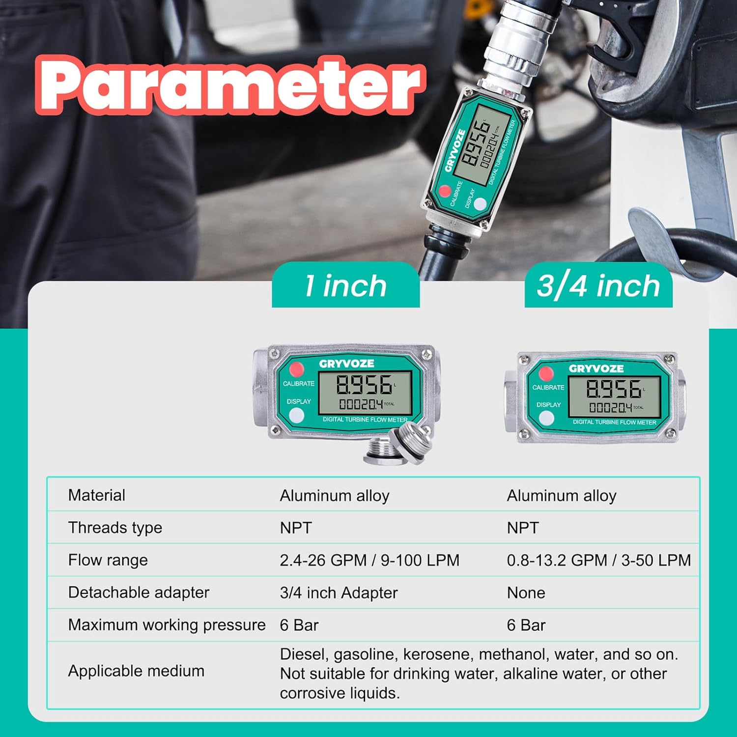
Image 8: Detailed parameter comparison for 1 inch and 3/4 inch models.
9. What's in the Box
- 1 PCS 1 Inch NPT Digital Fuel Flow Meter
- 2 PCS Detachable 3/4 Inch Adapters
10. Warranty and Support
For warranty information, technical support, or service inquiries, please refer to the product packaging or contact GRYVOZE customer service directly. Keep your purchase receipt for warranty claims.