1. Introduction
This manual provides essential information for the installation and use of the PODOFO 16-Pin Radio Wiring Harness. This harness is designed to facilitate the installation of an aftermarket Android head unit in compatible Toyota vehicles, while retaining key original features such as JBL amplifier support and steering wheel controls.
2. Compatibility
The PODOFO 16-Pin Radio Wiring Harness is compatible with various Toyota models equipped with a JBL amplifier. It is designed for aftermarket radios featuring a 16-pin power socket.
- Toyota Corolla: 2014-2018
- Toyota Camry: 2014-2018
- Toyota RAV4: 2013-2018
- Toyota Tundra: 2014-2018
- Toyota 4Runner: 2014-2018
- Toyota Prado: 2014-2019
- Toyota CHR: 2015-2018
- Toyota Highlander: 2015-2018
Important Compatibility Note:
Before purchase and installation, it is crucial to verify the interface on the back of your original car radio. If your old car radio has two 20-pin interfaces on the back, this harness is not compatible. Please refer to the image below for visual guidance.

Figure 2.1: Visual guide for Toyota radio compatibility. The top row shows compatible radio back panels. The bottom row shows incompatible panels with two 20-pin interfaces, marked "NOT Fit".

Figure 2.2: Detailed view of compatible and incompatible radio connectors. Ensure your original radio's connectors match the "Fit" examples to ensure proper function.
If you are uncertain about compatibility, it is recommended to provide the vehicle's model year and photos of the dashboard and the back of the original car radio to the manufacturer's technical support for verification.
3. Package Contents
The package includes the following item:
- 1 x PODOFO 16-Pin Radio Wiring Harness with Canbus Decoder

Figure 3.1: The PODOFO 16-Pin Radio Wiring Harness, including the Canbus decoder and various connectors.
4. Setup and Installation
This wiring harness is designed for plug-and-play installation with compatible aftermarket Android head units (those with a 16-pin power socket). No wire cutting is required for installation.
4.1. Pre-Installation Checks
- Verify Compatibility: Confirm your vehicle model and year are listed in the compatibility section (Section 2).
- Inspect Original Radio: Check the back of your original car radio to ensure it does not have two 20-pin interfaces, as this indicates incompatibility.
- Power Off Vehicle: Before beginning any electrical work, ensure the vehicle's ignition is off and the battery is disconnected to prevent electrical shorts or damage.
4.2. Installation Steps
- Remove Original Radio: Carefully remove your vehicle's existing car radio according to your vehicle's service manual.
- Connect Harness to Aftermarket Radio: Connect the 16-pin power socket of the PODOFO wiring harness to the corresponding 16-pin power socket on your aftermarket Android head unit.
- Connect Harness to Vehicle: Connect the vehicle-specific connectors on the PODOFO harness to the corresponding ports in your vehicle's dashboard wiring. These are designed for a direct fit.
- Connect Auxiliary Wires: Connect any auxiliary wires (e.g., for reverse camera, steering wheel control, amplifier trigger) as required by your aftermarket head unit and vehicle configuration. Refer to the pinout diagram for specific wire functions.
- Secure Connections: Ensure all connections are secure and properly seated.
- Test Functionality: Before fully reassembling the dashboard, reconnect the vehicle battery and test the aftermarket radio's functionality, including audio, steering wheel controls, and any connected accessories.
- Reassemble Dashboard: Once all functions are verified, carefully reassemble the dashboard components.

Figure 4.1: Detailed view of the wiring harness interfaces and a general pinout diagram. This diagram helps identify the function of each wire for proper connection.
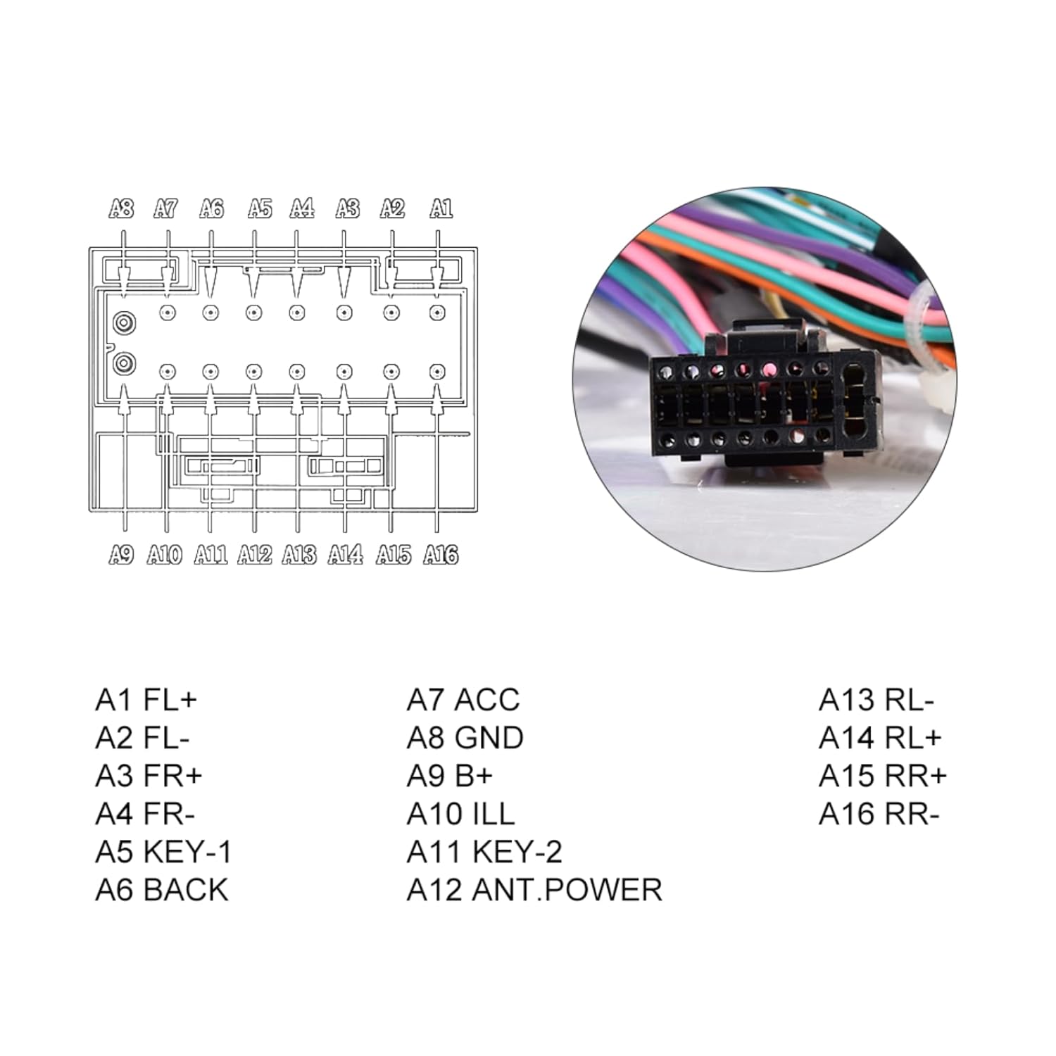
Figure 4.2: Close-up of the 16-pin connector and its pin assignments. This provides a clearer view of the wire functions for accurate installation.
| Pin | Function | Pin | Function | Pin | Function |
|---|---|---|---|---|---|
| A1 | FL+ (Front Left Speaker Positive) | A7 | ACC (Accessory Power) | A13 | RL- (Rear Left Speaker Negative) |
| A2 | FL- (Front Left Speaker Negative) | A8 | GND (Ground) | A14 | RL+ (Rear Left Speaker Positive) |
| A3 | FR+ (Front Right Speaker Positive) | A9 | B+ (Battery Positive) | A15 | RR+ (Rear Right Speaker Positive) |
| A4 | FR- (Front Right Speaker Negative) | A10 | ILL (Illumination) | A16 | RR- (Rear Right Speaker Negative) |
| A5 | KEY-1 (Steering Wheel Control 1) | A11 | KEY-2 (Steering Wheel Control 2) | ||
| A6 | BACK (Reverse Signal) | A12 | ANT.POWER (Antenna Power) |
5. Operating Features
This wiring harness is designed to integrate seamlessly with your aftermarket Android head unit, allowing it to utilize several original vehicle features.
5.1. JBL Amplifier Support
The harness includes a Canbus decoder that enables communication with the vehicle's original JBL amplifier system. This ensures that the aftermarket head unit can properly power and control the existing premium audio system.
5.2. Steering Wheel Control Retention
The integrated Canbus system also allows for the retention of your vehicle's original steering wheel controls. After installation, you may need to configure the steering wheel controls within your aftermarket head unit's settings menu to map the buttons correctly.
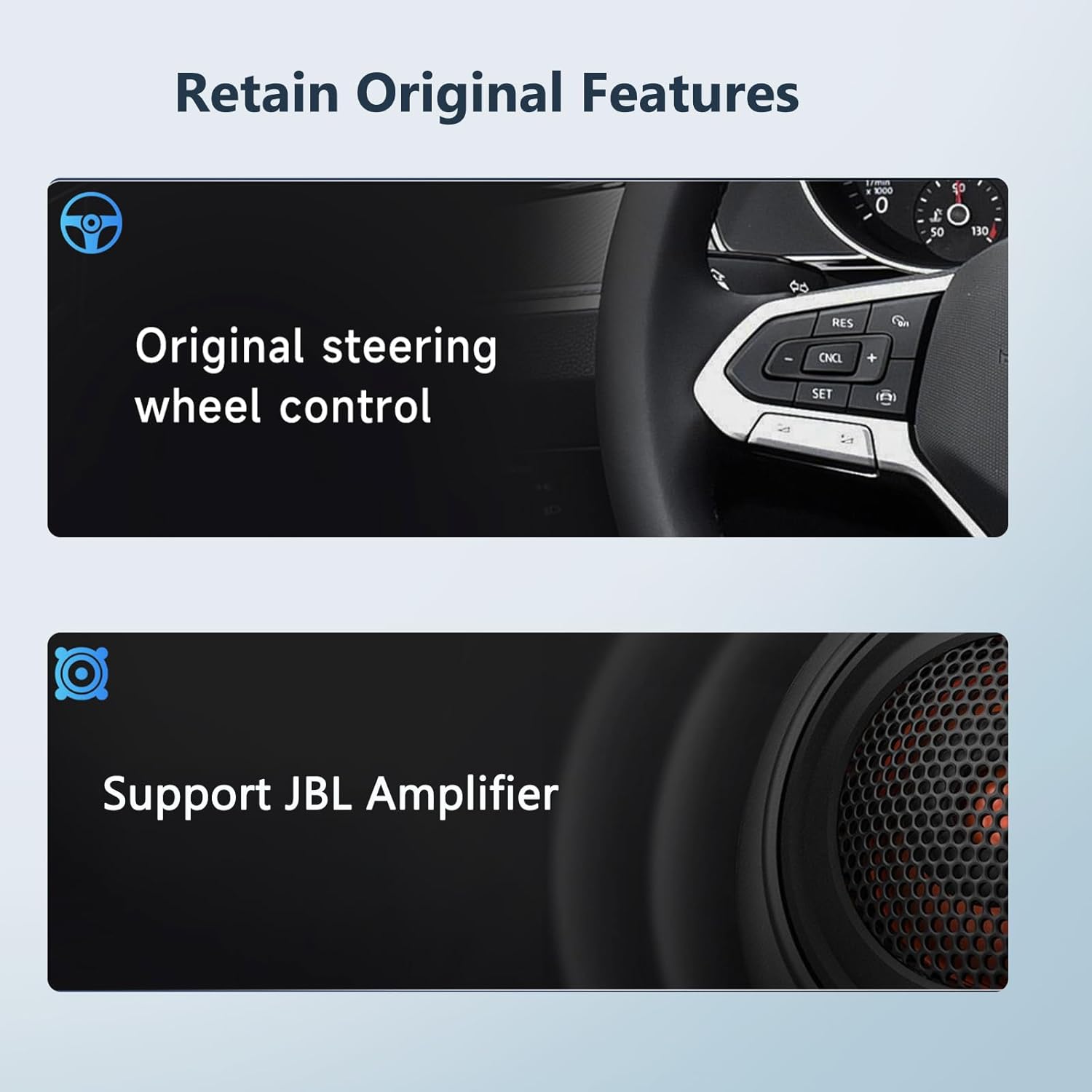
Figure 5.1: Visual representation of retained features: original steering wheel control functionality and support for the JBL amplifier system.
6. Maintenance
The PODOFO wiring harness is a passive component and requires minimal maintenance. Ensure all connections remain secure and free from moisture or physical damage. Periodically check for any loose connections if issues arise.
7. Troubleshooting
- No Power to Aftermarket Radio:
- Check all connections, especially the B+ (Battery Positive) and ACC (Accessory Power) wires, to ensure they are securely connected.
- Verify the vehicle's fuse for the radio is intact.
- Ensure the aftermarket radio itself is functional.
- No Sound or Poor Sound Quality:
- Confirm all speaker wires (FL+, FL-, FR+, FR-, RL+, RL-, RR+, RR-) are correctly connected to the aftermarket radio.
- Ensure the JBL amplifier is receiving power and is properly integrated via the Canbus decoder.
- Check the audio settings on your aftermarket head unit.
- Steering Wheel Controls Not Working:
- Verify that the KEY-1 and KEY-2 wires (if applicable to your radio) are correctly connected.
- Access the steering wheel control learning function in your aftermarket head unit's settings and follow the on-screen instructions to program the buttons.
- Ensure the Canbus decoder is properly connected and functioning.
- Reverse Camera Not Activating:
- Check the connection of the BACK (Reverse Signal) wire to the aftermarket radio's reverse input.
- Ensure the reverse camera itself is powered and properly connected to the head unit's video input.
Note:
If you encounter persistent issues, it is recommended to consult a professional car audio installer or contact PODOFO technical support.
8. Specifications
| Feature | Detail |
|---|---|
| Brand | podofo |
| Model | B0CXHZXV8B |
| Connector Type | IDC (16-pin power socket) |
| Material | Acrylonitrile Butadiene Styrene (ABS) |
| Compatibility | Toyota vehicles (specific models/years listed in Section 2) with JBL amplifier |
| Features | JBL amplifier support, Steering Wheel Control retention, Canbus integration |
| Installation | Plug and Play (no wire cutting) |
9. Warranty and Support
For warranty information and technical assistance, please contact PODOFO technical support. You can typically find support contact information through the seller's page on the platform where the product was purchased.
To find PODOFO's technical team for support:
- Navigate to the product page.
- Locate the "Sold by [Seller Name]" section (e.g., "Sold by Podofo Tech"). Click on the seller's name.
- On the seller's page, look for an "Ask a question" button or similar contact option.

Figure 9.1: Visual guide on how to locate and contact Podofo's technical support team via the product listing page.
For additional resources, you may visit the official Podofo Store.