1. Introduction and Overview
The ESP32-H2-DEV-KIT-N4 is an entry-level RISC-V microcontroller development board designed for various applications including smart home, industrial automation, healthcare, and consumer electronics. It integrates Bluetooth 5 and IEEE 802.15.4 (Zigbee 3.0 and Thread) wireless communication capabilities, offering superior RF performance.
This compact yet powerful board features the ESP32-H2-MINI-1-N4 module, equipped with a RISC-V 32-bit single-core processor operating at up to 96MHz, and includes 4MB of built-in Flash memory. It provides rich peripheral interfaces such as SPI, UART, I2C, I2S, LED PWM, and ADC. The onboard CH343 and CH334 USB HUB chips facilitate simultaneous USB and UART development via a single USB-C port. Its pinout is compatible with the ESP32-H2-DevKitM-1 development board, ensuring strong compatibility and expandability for various peripheral modules.
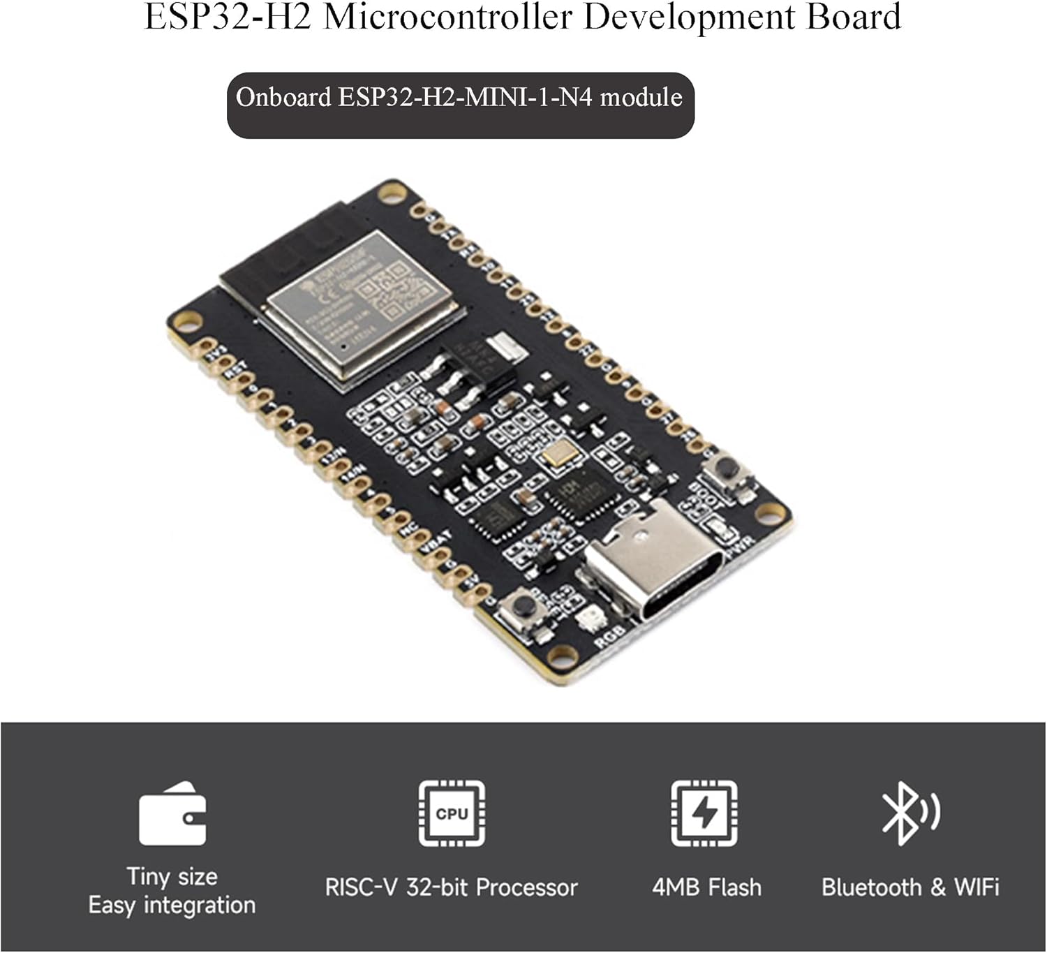
Figure 1.1: ESP32-H2 Microcontroller Development Board with key features.

Figure 1.2: ESP32-H2-DEV-KIT-N4 overview, showing the board with pre-soldered pin-headers.
2. Key Features
- Adopts ESP32-H2-MINI-1-N4 module with RISC-V 32-bit single-core processor, up to 96MHz main frequency, built-in 4MB Flash.
- Integrated Bluetooth 5 and IEEE 802.15.4 (Zigbee 3.0 and Thread) wireless communication, with superior RF performance. Its Bluetooth Low Energy subsystem supports Bluetooth 5 (LE) and Bluetooth Mesh.
- Type-C connector for ease of use.
- Onboard CH343 and CH334 chips enable USB and UART development via a single Type-C interface.
- Rich peripheral interfaces, compatible with the pinout of the ESP32-H2-DevKitM-1 development board, offering strong compatibility and expandability.
- Castellated module allows direct soldering to carrier boards.
- Supports various low-power operating states, with adjustable communication distance, data rate, and power consumption balance to meet diverse application requirements.
3. Product Components
The package includes the following items:
- ESP32-H2-DEV-KIT-N4 x1
- 40PIN male pinheader (black) x2
4. Setup Instructions
To begin using your ESP32-H2 Development Board, follow these general steps:
- Unpack the Board: Carefully remove the ESP32-H2-DEV-KIT-N4 board and the included pin headers from their packaging.
- Attach Pin Headers (Optional): If you plan to use the board with a breadboard or custom PCB, solder the provided 40PIN male pin headers to the board's pinout. Ensure proper alignment and secure connections.
- Connect to Computer: Use a USB-C cable to connect the ESP32-H2-DEV-KIT-N4 to your computer. The board will draw power from the USB connection.
- Driver Installation: Your operating system may automatically install necessary drivers for the CH343 and CH334 USB HUB chips. If not, you may need to manually install drivers, typically available from the chip manufacturer's website or the product's online resources.
- Access Online Resources: For detailed setup guides, examples, and development environment information, refer to the official online tutorial and development resources provided by the manufacturer. A common resource link is n9.cl/blqf74.
5. Operating Instructions
The ESP32-H2-DEV-KIT-N4 supports various development environments, including ESP-IDF and Arduino IDE. Here's a general guide to operating the board:
- Development Environment Setup: Install your preferred development environment (e.g., ESP-IDF or Arduino IDE) on your computer. Ensure all necessary toolchains and libraries for ESP32-H2 are installed.
- Code Development: Write your application code using the chosen development environment. The board supports Bluetooth 5 (LE), Bluetooth Mesh, Zigbee 3.0, and Thread for wireless communication.
- Upload Firmware: Connect the board to your computer via USB-C. Select the correct serial port in your IDE. Compile your code and upload the firmware to the ESP32-H2-MINI-1-N4 module.
- Monitoring and Debugging: Utilize the serial monitor in your IDE to view output from the board for debugging purposes. The onboard CH343 and CH334 chips facilitate reliable serial communication.
- Power Management: The board supports various low-power operating states. Optimize your code to utilize these states for applications requiring extended battery life.

Figure 5.1: Wireless communication support and development environment compatibility.
6. Onboard Resources and Pinout Definition
The ESP32-H2-DEV-KIT-N4 provides a range of onboard resources and a detailed pinout for interfacing with external components.
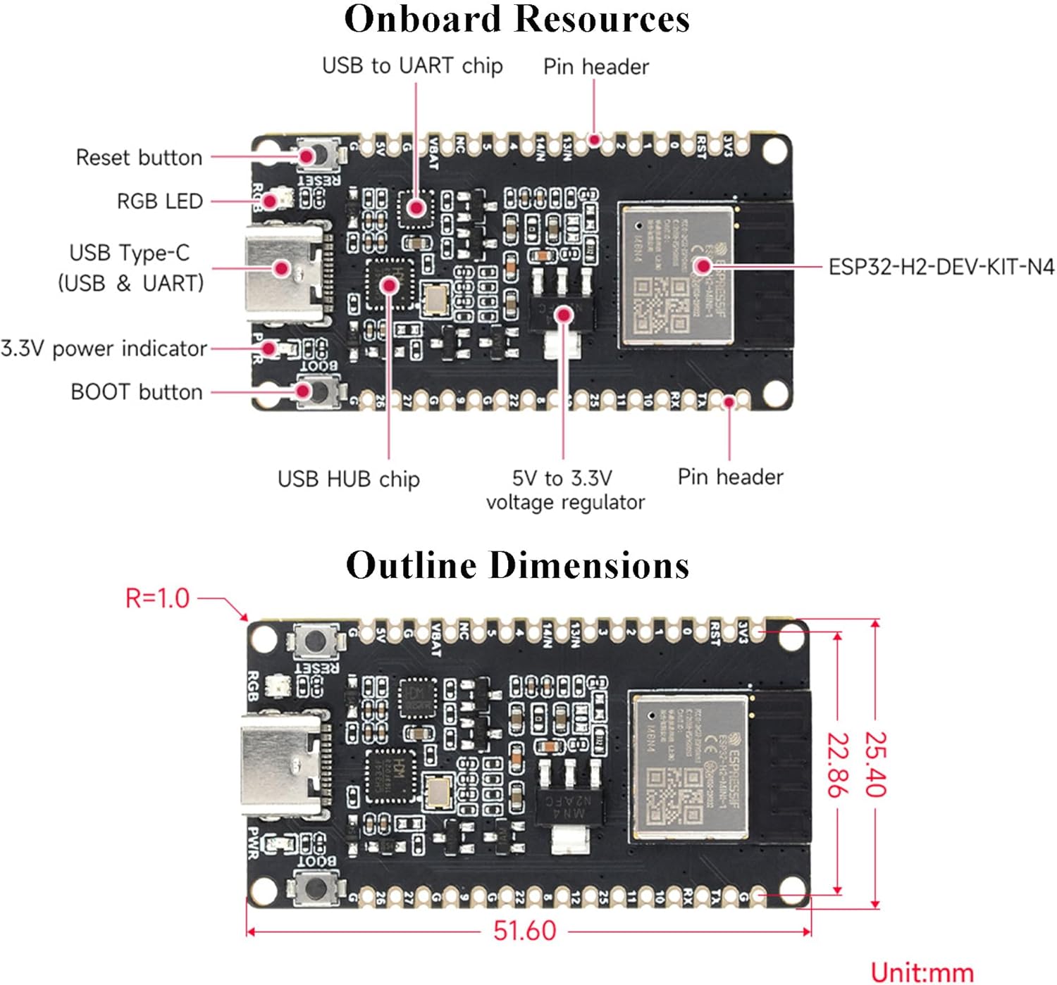
Figure 6.1: Onboard Resources of the ESP32-H2-DEV-KIT-N4.

Figure 6.2: Pinout Definition and Legend.
7. Function Block Diagram
The following diagram illustrates the internal functional blocks and their interconnections within the ESP32-H2-DEV-KIT-N4.

Figure 7.1: Function Block Diagram.
8. Specifications
| Feature | Specification |
|---|---|
| Processor | RISC-V 32-bit single-core, up to 96MHz |
| Flash Memory | 4MB |
| Wireless Connectivity | Bluetooth 5 (LE), IEEE 802.15.4 (Zigbee 3.0, Thread) |
| USB Interface | USB-C (for power, USB, and UART development) |
| USB HUB Chips | CH343, CH334 |
| Peripheral Interfaces | SPI, UART, I2C, I2S, LED PWM, ADC |
| Operating System Support | Linux (and compatible with various IDEs) |
| Dimensions | Approximately 1.8 x 0.86 x 0.11 inches (45.72 x 21.84 x 2.79 mm) |
| Weight | Approximately 0.64 ounces (18.14 grams) |
| Included Components | ESP32-H2-DEV-KIT-N4 x1, 40PIN male pinheader (black) x2 |
9. Troubleshooting
If you encounter issues with your ESP32-H2 Development Board, consider the following:
- Connection Issues: Ensure the USB-C cable is securely connected to both the board and your computer. Try a different USB port or cable.
- Driver Problems: Verify that the correct drivers for the CH343/CH334 chips are installed. Check your computer's device manager for any unrecognized devices.
- Firmware Upload Failure: Confirm that the correct board and serial port are selected in your development environment. Ensure the board is in programming mode if required (often by holding the BOOT button while pressing and releasing RESET, then releasing BOOT).
- Code Errors: Review your code for syntax errors or logical flaws. Use debugging tools and serial output to identify the source of the problem.
- Power Supply: While USB provides power, ensure your computer's USB port can supply sufficient current, especially if powering external components.
- Online Resources: Consult the official online tutorials and community forums for common issues and solutions.
10. Maintenance
To ensure the longevity and optimal performance of your ESP32-H2 Development Board, follow these maintenance guidelines:
- Handle with Care: Avoid dropping the board or subjecting it to excessive physical stress.
- Keep Clean: Periodically clean the board with a soft, dry brush or compressed air to remove dust and debris. Avoid using liquids.
- Storage: Store the board in an anti-static bag or container when not in use to protect it from electrostatic discharge and physical damage.
- Environmental Conditions: Operate and store the board within recommended temperature and humidity ranges to prevent damage to electronic components.
- Power Off When Not in Use: Disconnect the board from power when not actively developing or operating to prevent unnecessary wear and power consumption.
11. Warranty and Support
For information regarding product warranty, technical support, or returns, please refer to the documentation provided at the time of purchase or contact Wonrabai customer service directly. Online resources and community forums can also provide valuable assistance for development-related queries.
Manufacturer: Wonrabai
ASIN: B0CXF1RZ49