Pilipane B0CWV71P6B
Pilipane Stand Alone Access Control Keypad User Manual
Model: B0CWV71P6B
1. Introduction
This manual provides comprehensive instructions for the installation, operation, and maintenance of your Pilipane Stand Alone Access Control Keypad. This system is designed to provide secure and automated access control for various environments, including homes, offices, factories, and communities. Please read this manual thoroughly before installation and use to ensure proper functionality and safety.
The system supports multiple access methods: RFID key card, password, or a combination of both. It features a built-in ID card reader module and allows for 3-6 digit passwords.
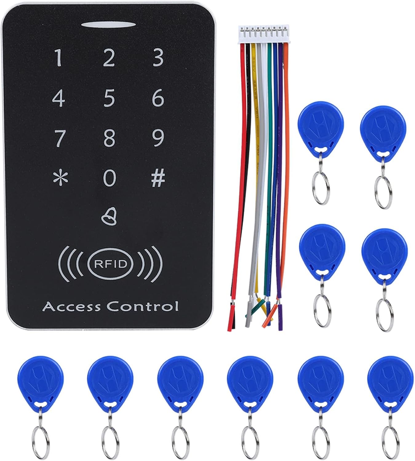
2. Package Contents
Verify that all items listed below are present in your package:
- 1 x RFID One-door Access Controller (Keypad Unit)
- 10 x Key Fobs (RFID Cards)
- 1 x Connection Cable
- 1 x English User Manual (this document)
3. Specifications
| Feature | Specification |
|---|---|
| Material | PVC |
| Working Voltage | DC 12V |
| Color | Silver + Black |
| Identification Way | Smart Card (RFID) |
| Inductive Way | ID Card + Password |
| Card Reading Distance | 2-10cm |
| Storage Capacity | 1000 Users |
| Unlock Type | ID Card / Password / ID Card + Password |
| Dimensions | Approx. 11.8 x 7.6 x 2.1 cm (4.6 x 3.0 x 0.8 inches) |
| Weight | Approx. 149g (5.3oz) |

4. Setup and Installation
4.1 Wiring Diagram
Proper wiring is crucial for the correct operation of the access control system. Refer to the internal circuit board for connection points.

Wiring Connections:
- +12V: Connect to the positive terminal of a DC 12V power supply.
- GND: Connect to the negative terminal of the DC 12V power supply.
- PUSH: Connect to the exit button.
- BELL: Connect to an external door bell.
- NC (Normally Closed): Connect to the NC terminal of an electric lock.
- COM (Common): Connect to the COM terminal of an electric lock.
- NO (Normally Open): Connect to the NO terminal of an electric lock.
- OPEN: Connect to the door sensor (if applicable).
Ensure all connections are secure and correctly matched to avoid damage to the device or connected components.
4.2 Initial Power-Up
After completing all wiring, apply DC 12V power to the unit. The keypad should illuminate, indicating it is ready for programming.
5. Operation and Programming
5.1 Default Settings
- Default Administrator Password: 123456
- Default Door Open Mode: Card or Password
5.2 Entering Programming Mode
- Press *.
- Enter the Administrator Password (default: 123456).
- Press #.
- The indicator light will change, confirming entry into programming mode.
5.3 Changing Administrator Password
- Enter Programming Mode.
- Press 0.
- Enter the new 6-digit Administrator Password.
- Press # to confirm.
- Exit Programming Mode by pressing *.
5.4 Adding User Cards (RFID Fobs)
- Enter Programming Mode.
- Press 1.
- Present the RFID card to be added to the reader. The unit will beep to confirm.
- Repeat for additional cards.
- Exit Programming Mode by pressing *.

5.5 Deleting User Cards
- Enter Programming Mode.
- Press 2.
- Present the RFID card to be deleted to the reader. The unit will beep to confirm deletion.
- Repeat for additional cards.
- Exit Programming Mode by pressing *.
5.6 Setting User Passwords
Each user can have a 3-6 digit password. Passwords are associated with user IDs, which are automatically assigned when a card is added.
- Enter Programming Mode.
- Press 3.
- Enter the User ID (e.g., 001 for the first card added).
- Press #.
- Enter the new 3-6 digit password.
- Press # to confirm.
- Exit Programming Mode by pressing *.

5.7 Setting Door Open Mode
The system supports three door open modes:
- Card Only: Access granted by presenting a registered RFID card.
- Password Only: Access granted by entering a registered password.
- Card + Password: Access granted by presenting a registered RFID card followed by its associated password.

- Enter Programming Mode.
- Press 4 for Card Only mode.
- Press 5 for Password Only mode.
- Press 6 for Card + Password mode.
- Press # to confirm.
- Exit Programming Mode by pressing *.
5.8 Reset Function
To reset the device to factory default settings (Administrator Password: 123456, Door Open Mode: Card or Password, all user data deleted):
- Disconnect power from the unit.
- Locate the reset button or jumper on the circuit board (refer to Image 3).
- While holding the reset button/jumper, reconnect power.
- Hold for approximately 5 seconds until you hear a long beep.
- Release the button/jumper. The system is now reset.
6. Maintenance
- Cleaning: Use a soft, dry cloth to clean the keypad surface. Avoid abrasive cleaners or solvents.
- Power Supply: Ensure a stable DC 12V power supply is used. Fluctuations can affect performance.
- Data Retention: The device utilizes integrated circuit techniques to prevent data loss during power failures, ensuring settings and user data are retained.
- Regular Testing: Periodically test all access methods (card, password, card+password) to ensure proper functionality.
7. Troubleshooting
| Problem | Possible Cause | Solution |
|---|---|---|
| Keypad does not power on. | No power, incorrect wiring, faulty power supply. | Check DC 12V power connection. Verify wiring according to diagram. Test power supply. |
| Door does not unlock with valid card/password. | Incorrect door open mode, card/password not registered, faulty lock connection. | Verify door open mode setting. Re-register card/password. Check lock wiring (NC/NO/COM). |
| Cannot enter programming mode. | Incorrect administrator password. | Ensure correct administrator password is used. If forgotten, perform a factory reset. |
| RFID card not detected. | Card not registered, card damaged, interference. | Ensure card is registered. Try a different card. Avoid placing metal objects near the reader. |
8. Warranty and Support
For warranty information or technical support, please refer to the seller's policy or contact the manufacturer, Pilipane, directly through their official channels. Keep your purchase receipt as proof of purchase.
Manufacturer: Pilipane
Ask a question about this manual
Ask about setup, troubleshooting, compatibility, parts, safety, or missing instructions. Manuals+ will review the question and use this page’s manual context to help answer it.