Cotether 13398-DO
Cotether 13398-DO Dual Motor Synchronous Velocity Slide Controller User Manual
1. Introduction
This manual provides comprehensive instructions for the installation, operation, and troubleshooting of the Cotether 13398-DO Dual Motor Synchronous Velocity Slide Controller. This controller is designed to manage the extension and retraction of RV in-wall slide-out mechanisms, ensuring smooth and synchronized movement. It is compatible with Lippert In-Wall slide-outs and replaces the 13398-C2 version.
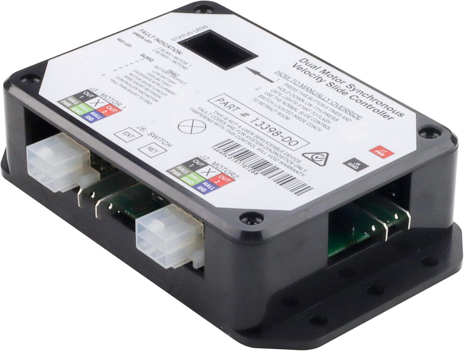
Image 1.1: Cotether 13398-DO Dual Motor Synchronous Velocity Slide Controller.
2. Product Overview
2.1 Component Identification
Familiarize yourself with the key components of the controller:

Image 2.1: Component Identification Diagram.
- Status LEDs: Two LEDs (one green, one red) indicate the current controller status and fault conditions.
- Mode Button: Used to engage the electronic manual override function.
- Power Connection (J7 PWR, J8 GND): 12V DC input. The unit operates within a voltage range of 8V DC to 18V DC.
- Motor 1 Connector (J3): Power and encoder input for motor 1.
- Motor 2 Connector (J2): Power and encoder input for motor 2.
- Switch Connection (J6): Spade connection for the slide-out switch.
3. Installation
3.1 Wiring Diagram
Refer to the following diagram for proper wiring of the controller within your RV's slide-out system. Ensure all connections are secure and correctly polarized.
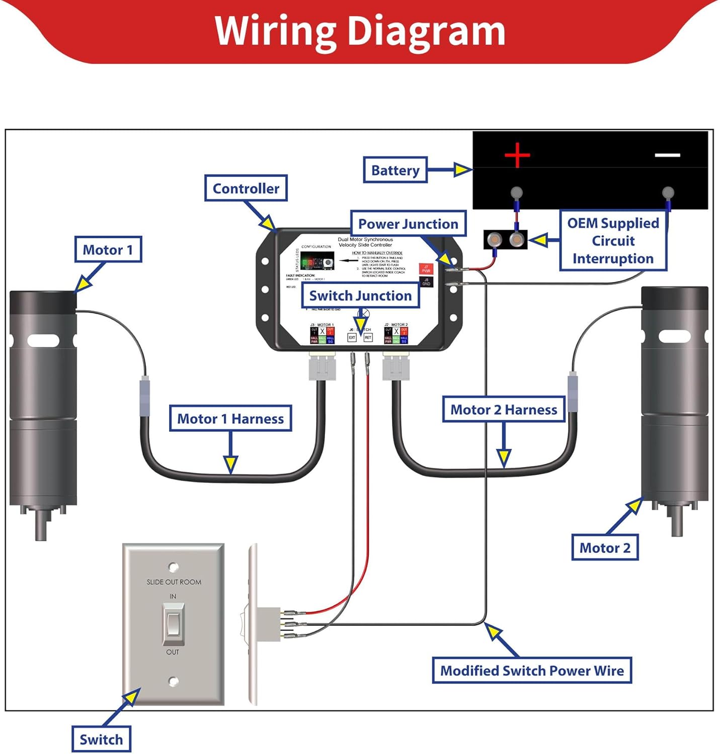
Image 3.1: Typical Wiring Diagram.
Important: This is a non-serviceable device. Tampering with this control will void the warranty. Always disconnect battery power before attempting any wiring or installation.
3.2 Product Dimensions
Consider the following dimensions for appropriate mounting and clearance:

Image 3.2: Product Dimensions.
- Length: 5.5 inches
- Width: 3.3125 inches
- Height: 1.375 inches
4. Operation
4.1 Normal Operation
The controller manages the extension and retraction of the RV slide-out via the standard slide control switch located inside the coach. It ensures synchronized movement of both motors for smooth operation.
4.2 Manual Override
In the event of a system malfunction, the controller features a manual override function:

Image 4.1: Manual Override Button and Status LEDs.
- Press the Mode Button 6 times and hold down on the 7th press. Continue holding until the status lights begin to flash.
- Use the normal slide control switch located inside the coach to retract the room.
4.3 LED Status Indicators
The green and red LEDs provide visual feedback on the controller's status and any detected faults:
- Green LED:
- 1 Blink = Motor 1 activity
- 2 Blinks = Motor 2 activity
- Red LED (Fault Indication):
- 2 Blinks = Battery Dropout
- 3 Blinks = Low Battery
- 4 Blinks = High Battery
- 5 Blinks = Excessive Motor Current
- 6 Blinks = Motor Short Circuit
- 8 Blinks = Wire Short Between Controller and Motor
- 9 Blinks = Hall Power Short to Ground
5. Troubleshooting
5.1 Error Code Description
The red LED fault indications correspond to specific error codes. Use the table below to diagnose issues:

Image 5.1: Error Code Description Table.
| Error Code | Name | Description |
|---|---|---|
| 2 | Battery drop out | Battery capacity low enough to drop below 6 volts while running or short in switch wiring. |
| 3 | Low battery | Voltage below 8 volts at start of cycle. |
| 4 | High battery | Voltage greater than 18 volts. |
| 5 | Excessive motor current | High amperage, also indicated by 1 side of slide continually stalling. |
| 6 | Motor short circuit | Motor or wiring to motor has shorted out. |
| 8 | Wire short between controller and motor | Encoder is not providing a signal. This is usually a wiring problem. |
| 9 | Hall power short to ground | Power to encoder has been shorted to ground. This is usually a wiring problem. |
6. Specifications
- Manufacturer: Cotether
- Model Number: 13398-DO
- Input Voltage: 12 Volts DC (Operating range: 8V DC to 18V DC)
- Item Weight: 7.8 ounces
- Product Dimensions: 5.21 x 3.22 x 1.25 inches
- Display Type: LED (for status and fault indication)
- Safety Features: Overcurrent protection, temperature monitoring
- Construction: High-quality FR-2 copper-clad laminate, upgraded solid capacitors, SR waterproof coating
7. What's in the Box
The product package includes:
- 1 x Dual Motor Slide Controller (Model 13398-DO)
8. Warranty and Support
For warranty information or technical support, please refer to the documentation provided with your purchase or contact Cotether customer service directly. Ensure you have your product model number (13398-DO) and purchase details available when contacting support.
Ask a question about this manual
Ask about setup, troubleshooting, compatibility, parts, safety, or missing instructions. Manuals+ will review the question and use this page’s manual context to help answer it.