NCLTHS Electric Magnetic Door Lock Kit
NCLTHS 1200lb Electric Magnetic Door Lock Kit User Manual
Model: Electric Magnetic Door Lock Kit (500Kg / 1200LB Kits)
Brand: NCLTHS
1. Introduction
This manual provides comprehensive instructions for the installation, operation, and maintenance of your NCLTHS 1200lb Electric Magnetic Door Lock Kit. This access control system is designed to provide secure and convenient entry management for various indoor applications. Please read this manual thoroughly before installation and operation to ensure proper functionality and safety.
2. Safety Information
- Electrical Safety: Installation involves electrical wiring. Ensure power is disconnected before performing any wiring. If you are not comfortable with electrical work, consult a qualified electrician.
- Voltage: The system operates on 12V DC. Ensure the power supply unit is correctly connected to a 110-240VAC source and outputs 12V DC.
- Indoor Use Only: This product is recommended for indoor use. Exposure to outdoor elements may damage components and void warranty.
- Secure Mounting: Ensure all components, especially the magnetic lock and armature plate, are securely mounted to prevent accidental detachment.
- Hazardous Voltage: The power supply unit contains hazardous voltage. Do not open the power supply cover.
3. Package Contents
Verify that all components listed below are included in your package:

Figure 3.1: Overview of all included components in the NCLTHS 1200lb Electric Magnetic Door Lock Kit. This includes the magnetic lock, power supply, RFID keypad, doorbell, remote receiver with two remotes, five RFID keyfobs, and an exit button, along with mounting hardware.
- 1 x 1200LBS Electric Magnetic Lock
- 1 x Access Control Keypad (RFID Keypad)
- 1 x Doorbell Chime
- 2 x Remote Transmitters
- 1 x Remote Receiver
- 5 x RFID Keyfobs (ID Cards)
- 1 x Power Supply Control Unit (110-240VAC to 12VDC)
- 1 x Push to Exit Button
- 1 x English User Manual (this document)
- Mounting Hardware (screws, anchors, etc.)
4. Setup and Installation
Proper installation is crucial for the security and functionality of the access control system. Ensure all safety precautions are followed.
4.1 Component Overview

Figure 4.1.1: The power supply unit, showing input (AC110V-240V) and output (DC12V/4A) terminals, along with connections for N.O., GND, N.C., +12V, GND, PUSH, -CTRL, and +CTRL.

Figure 4.1.2: The RFID keypad, featuring a numeric input pad, asterisk and hash keys, and a doorbell button icon.
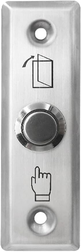
Figure 4.1.3: The push to exit button, typically installed on the inside of the door for convenient egress.

Figure 4.1.4: The remote receiver module and two handheld remote transmitters for wireless access control.

Figure 4.1.5: A stack of RFID keyfobs (ID cards) used for proximity access with the keypad.
4.2 Wiring Diagram
Refer to the following diagrams for correct wiring connections. Ensure all connections are secure and insulated.

Figure 4.2.1: Comprehensive wiring diagram illustrating the interconnection of all system components, including the magnetic lock, power supply, exit button, remote control module, access control keypad, and doorbell.

Figure 4.2.2: Detailed wiring connections for the power supply, access control keypad, remote control module, and doorbell, with color-coded wires for clarity.
Key Wiring Points:
- Connect the magnetic lock to the power supply's V+ and V- terminals.
- Connect the exit button to the PUSH and GND terminals on the power supply.
- Connect the remote receiver to the power supply's +12V, GND, COM, and NO terminals as indicated in the diagram.
- Connect the access control keypad to the power supply's 12V, GND, NO, COM, and BELL terminals.
- Connect the doorbell chime to the BELL terminals on the access control keypad.
- Ensure the power supply is connected to a 110-240VAC source.
4.3 Magnetic Lock Installation
- Determine the mounting location for the magnetic lock on the door frame and the armature plate on the door.
- Mount the magnetic lock securely to the door frame using appropriate screws and anchors. Ensure it is level and aligned with the intended position of the armature plate.
- Attach the armature plate to the door, ensuring it aligns perfectly with the magnetic lock when the door is closed. Use the provided hardware.
- Verify that the magnetic lock and armature plate make full contact when the door is closed, providing maximum holding force.
Note: Mounting brackets may be required for certain door types (e.g., glass doors, narrow frames) and are not always included in the standard kit. Please check your specific installation requirements.
4.4 Keypad Programming
The access control keypad allows for programming user codes and RFID cards. The default master code is typically 123456 (or similar, refer to the specific keypad manual if provided separately). If the default code does not work, consult the manufacturer for assistance.
General Programming Steps (may vary slightly by keypad model):
- Enter Programming Mode: Press * then enter the Master Code (e.g., 123456) then #. The indicator light should change (e.g., turn green or flash).
- Add User Code: In programming mode, press 1 (or a similar key for adding users), then enter a 4-6 digit user code, then #. Repeat for additional user codes.
- Add RFID Card: In programming mode, press 2 (or a similar key for adding cards), then present the RFID card to the keypad. The keypad should beep to confirm. Repeat for additional cards.
- Exit Programming Mode: Press * to exit programming mode.
Note: Detailed programming instructions for specific keypad functions (e.g., deleting users, changing master code, setting access modes) are usually provided in a separate, dedicated keypad manual. If you encounter difficulties, refer to that specific manual or contact support.
4.5 Remote Control Setup
To pair the remote transmitters with the receiver:
- Ensure the remote receiver is powered and connected to the system as per the wiring diagram.
- Locate the learning button on the remote receiver module.
- Press and hold the learning button until an indicator light on the receiver illuminates or flashes.
- While the indicator is active, press any button on the remote transmitter you wish to pair. The receiver's indicator should confirm successful pairing (e.g., flash rapidly, then turn off).
- Repeat for any additional remote transmitters.
5. Operating Instructions
5.1 Unlocking with RFID Keypad
- Using a User Code: Enter your programmed 4-6 digit user code on the keypad, then press #. The magnetic lock will disengage for a set duration (typically 3-5 seconds).
- Using an RFID Card: Present a programmed RFID card to the keypad's reader area. The magnetic lock will disengage for a set duration.
5.2 Unlocking with Remote Control
Press the unlock button on a paired remote transmitter. The magnetic lock will disengage for a set duration.
5.3 Exiting with Push Button
From the inside, press the push to exit button. The magnetic lock will disengage, allowing you to open the door.
5.4 Doorbell Function
Press the doorbell button on the RFID keypad. The connected doorbell chime will sound.
6. Maintenance
- Cleaning: Wipe down the keypad and magnetic lock surfaces with a soft, dry cloth. Avoid abrasive cleaners or solvents.
- Cable Inspection: Periodically check all wiring for signs of wear, damage, or loose connections. Ensure all connections remain secure.
- Magnetic Lock Alignment: Ensure the magnetic lock and armature plate remain properly aligned for optimal holding force. Adjust if necessary.
- Power Supply Check: Verify the power supply unit is functioning correctly and providing stable 12V DC output.
7. Troubleshooting
| Problem | Possible Cause | Solution |
|---|---|---|
| Magnetic lock does not engage/hold securely. |
|
|
| Keypad does not respond or accept codes/cards. |
|
|
| Remote control does not unlock the door. |
|
|
| Doorbell does not chime. |
|
|
8. Specifications
| Feature | Detail |
|---|---|
| Brand | NCLTHS |
| Model Name | Access Control System |
| Lock Type | Combination Lock (Magnetic Lock) |
| Holding Force | 1200lb (500Kg) |
| Material | Aluminum |
| Power Source | Corded Electric |
| Input Voltage | 110-240VAC |
| Output Voltage | 12 Volts (DC) |
| Special Feature | Auto-Lock |
| Recommended Use | Indoor |
| Item Dimensions (L x W x H) | 12 x 8 x 3.5 inches |
| Item Weight | 11.68 Pounds |
| Control Method | Touch (Keypad), Hand Control (Remote) |
| UPC | 716841008753 |
9. Warranty and Support
For warranty information, please refer to the documentation provided with your purchase or contact the retailer. For technical support, assistance with installation, or troubleshooting beyond the scope of this manual, please contact NCLTHS customer service through the platform where the product was purchased or visit the official NCLTHS website for contact details.
When contacting support, please have your product model number (Electric Magnetic Door Lock Kit) and purchase details readily available.
Ask a question about this manual
Ask about setup, troubleshooting, compatibility, parts, safety, or missing instructions. Manuals+ will review the question and use this page’s manual context to help answer it.