1. Introduction
This manual provides detailed instructions for the installation, setup, operation, and maintenance of the COKYIS CH702 Digital PID Temperature Controller. The CH702 is an intelligent temperature regulator designed for precise temperature control in various industrial and scientific applications. It features dual output (Relay/SSR) and supports multiple input types.
2. Safety Information
Please read all safety warnings and instructions carefully before installation and operation to prevent personal injury or damage to the device. Keep this manual for future reference.
- Ensure the power supply voltage matches the controller's specifications (AC85-265V).
- Disconnect power before making any wiring connections or performing maintenance.
- Installation should be performed by qualified personnel.
- Do not operate the controller in environments with corrosive gases or excessive humidity (30-85% RH).
- Avoid exposing the device to direct sunlight, high temperatures, or strong vibrations.
3. Product Overview
The COKYIS CH702 is a compact and versatile digital PID temperature controller. It features a clear 8-segment 4-digital display for process value (PV) and set value (SV), along with LED indicators for output and alarm status.
3.1. Dimensions and Features

Image 1: Front and side view of the CH702 controller, showing its 72x72mm front panel and 78mm depth. The cut-out size for mounting is 68x68mm. It indicates universal input and Relay+SSR output with 1 alarm.
- Model: CH702FK02-MV*AN
- External Dimensions: 72x72x78 mm
- Perforation Dimensions (Cut-out): 68x68 mm
- Display: 8-segment 4-digital display for PV and SV, LED indicators for AT, OUT1, OUT2, ALM1, ALM2.
- Control Buttons: SET, AT, Shift, Up, Down.
3.2. Rear Terminal Connections

Image 2: Rear view of the CH702 controller, displaying the screw terminal blocks for power, sensor input, and output connections. Specific terminal numbering is visible.
The rear panel provides clearly labeled screw terminals for power input, sensor input, and control outputs. Refer to the wiring diagram in the Installation section for detailed connections.
4. Specifications
| Parameter | Value |
|---|---|
| Model Series | CH series short type |
| Supply Voltage | AC85-265V 50/60Hz |
| Measurement Precision | ±0.5%FS |
| Temperature Measurement Range | 0-1300°C (32-2372°F) (Note: Default factory setting is 0-400°C. To achieve 0-1300°C, the thermocouple and controller input type must be changed accordingly.) |
| Input Types | K, E, J, PT100, CU50 |
| Available Output Types | Electromagnetic relay + SSR |
| Control Mode | Industrial-grade expert auto-tuning PID technology |
| Resolution | 14 bit |
| Indication Method | 8-segment 4-digital display and LED indication |
| Alarm Quantity | 1 or 2 (CH702 with 1 Alarm variant) |
| Cold Junction Compensation Error | ±2°C (0-50°C within software correction) |
| Insulation Resistance | >500MΩ (500VDC) |
| Operating Environment | 0 to 50°C (32 to 122°F), 30-85% RH (non-condensing, non-corrosive gases) |
5. Installation
5.1. Mounting
The CH702 controller is designed for panel mounting. Ensure the panel cut-out dimensions are 68x68mm. Insert the controller into the opening and secure it using the provided mounting brackets.
5.2. Wiring Diagram
Refer to the wiring diagram typically found on the side of the unit or in the packaging. Ensure all connections are secure and correct before applying power.
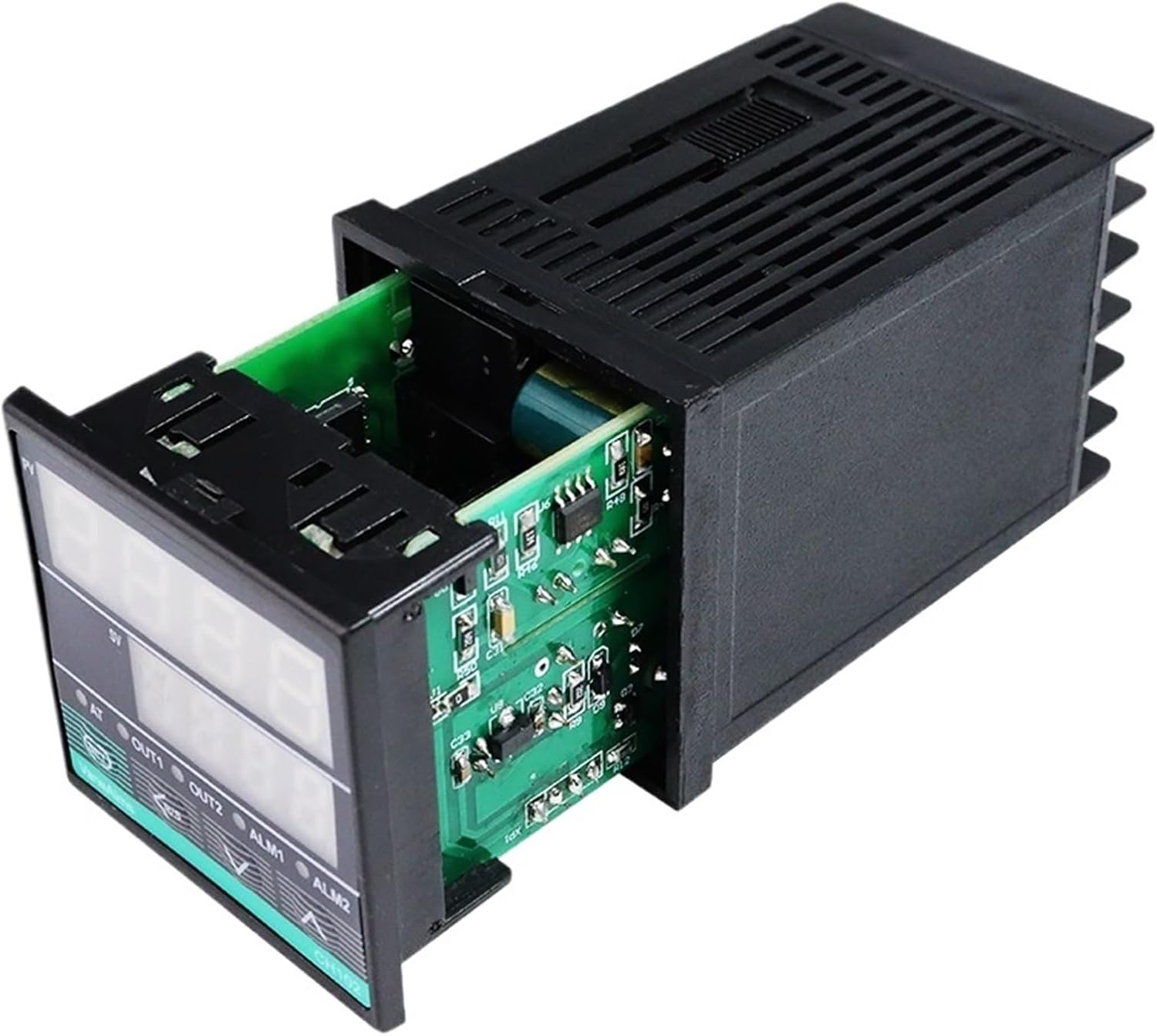
Image 3: The main unit of the COKYIS CH702 controller. This image helps visualize the overall product for wiring reference, though a dedicated wiring diagram is recommended for precise connections.
- Power Supply: Connect AC85-265V to the designated power terminals.
- Sensor Input: Connect your chosen thermocouple (K, E, J) or RTD (PT100, CU50) to the input terminals. Ensure correct polarity for thermocouples.
- Output 1 (Relay): Connect the load to the relay output terminals.
- Output 2 (SSR): Connect the Solid State Relay (SSR) control input to the SSR output terminals.
- Alarm Output(s): Connect alarm indicators or devices to the alarm output terminals.
6. Initial Setup and Parameter Configuration
After wiring, power on the controller. The display will show the current process value (PV) and set value (SV).
6.1. Setting the Set Value (SV)
- Press the SET button once. The SV display will flash.
- Use the Up and Down arrow buttons to adjust the desired set temperature.
- Use the Shift button to move the cursor for faster adjustment.
- Press SET again to confirm and save the new SV.
6.2. Accessing Parameter Settings
To access advanced parameters, press and hold the SET button for approximately 3-5 seconds until the first parameter code appears on the PV display.
- Use Up and Down to navigate through parameters.
- Press SET to view the value of a parameter.
- Use Up, Down, and Shift to change the parameter value.
- Press SET to save the new value and move to the next parameter.
- To exit the parameter setting mode, press and hold SET again, or wait for the controller to time out.
6.3. Important Parameters (Consult full manual for complete list)
- Input Type (e.g., "InP"): Set this to match your connected sensor (K, E, J, PT100, CU50). Incorrect setting will result in inaccurate readings.
- Control Mode (e.g., "CtL"): Select PID control or ON/OFF control.
- Alarm Settings (e.g., "AL1", "AH1"): Configure alarm type and set points.
- Auto-Tuning (AT): Press the AT button to initiate auto-tuning for optimal PID parameters. The AT indicator will flash during auto-tuning.
7. Operation
Once configured, the controller will automatically regulate the temperature according to the set value (SV) using its PID algorithm. The PV display shows the current temperature, and the SV display shows the target temperature.
- OUT1/OUT2 Indicators: These LEDs illuminate when the respective output (Relay or SSR) is active.
- ALM1/ALM2 Indicators: These LEDs illuminate when an alarm condition is met.
- AT Indicator: Flashes during auto-tuning.
8. Maintenance
The CH702 controller requires minimal maintenance. Regular checks can ensure optimal performance.
- Cleaning: Gently wipe the display and casing with a soft, dry cloth. Do not use abrasive cleaners or solvents.
- Connections: Periodically check all wiring connections for tightness and signs of corrosion.
- Environment: Ensure the operating environment remains within specified temperature and humidity ranges.
9. Troubleshooting
| Problem | Possible Cause | Solution |
|---|---|---|
| No display/Power off | No power supply or incorrect wiring. | Check power connections and voltage. Ensure AC85-265V is supplied. |
| Inaccurate temperature reading | Incorrect input type setting; faulty sensor; loose sensor connection. | Verify "InP" parameter matches sensor type. Check sensor wiring and replace if faulty. |
| Controller not heating/cooling | Output wiring incorrect; faulty relay/SSR; control mode issue; SV not set. | Check output wiring. Test relay/SSR. Verify control mode and SV. |
| Temperature overshoot/undershoot | PID parameters not optimized. | Perform auto-tuning (press AT button) to optimize PID parameters. |
10. Warranty and Support
COKYIS products are manufactured to high-quality standards. For warranty information and technical support, please refer to the documentation provided with your purchase or contact your vendor. Keep your purchase receipt as proof of purchase.
For further assistance, please visit the COKYIS official website or contact customer service.
