1. Introduction
This manual provides detailed instructions for the installation, operation, and maintenance of your Astibym Blind Spot Detection Monitoring System Kit. This advanced system is designed to enhance driving safety by providing alerts for vehicles in your blind spots, assisting with lane changes, and offering rear cross-traffic and door opening warnings. It is a universal 12V system compatible with all vehicles.
The system features one transmitting and multiple receiving sensors for accurate monitoring and is built with IP67 rating for all-weather durability, ensuring optimal performance in various conditions such as rain, fog, and at night.

2. Safety Information
Please read all instructions carefully before installation and operation. Improper installation or use may lead to system malfunction or vehicle damage. Always ensure the vehicle's power is disconnected before performing any electrical work. Professional installation is recommended. This system is an aid and does not replace safe driving practices or the driver's responsibility to check mirrors and surroundings.
3. Package Contents
Verify that all components listed below are present in your package:
- 2 x BSD Sensors
- 2 x Notifiers (LED indicators)
- 1 x Buzzer
- 4 x Wiring Harnesses
- 2 x Install Brackets
- 8 x Bind (Cable Ties)
- 1 x Probe Feet (Angle Ruler)
- 8 x Screws

4. Setup and Installation
The system is designed for discreet mounting on both sides of the rear bumper and does not require an OBD connection. Follow these steps for installation:
- Prepare the Vehicle: Disconnect the vehicle's battery.
- Remove Rear Bumper Components:
- Remove the back box.
- Remove the left and right taillight screws with a screwdriver, then carefully remove the taillights.
- Locate the firmware from the side of the wheel. Secure the firmware from left to right or right to left, and remove it.
- After the firmware is removed, directly remove the back box.
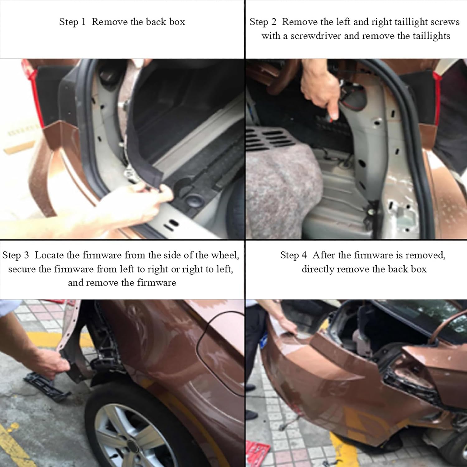
Visual guide for removing the back box, taillights, and firmware to access the installation area. - Install Radar Sensors:
- Install the left and right radar sensors on the rear bumper using the provided brackets and screws.
- Ensure the radar bracket is parallel to the rear bar contact surface.
- The radar should be installed approximately 65cm (25.6 inches) above the ground.
- Use the angle ruler (probe feet) on the radar surface. The arrow on the angle ruler should be forward parallel to the longitudinal direction of the wheel.
- Looking from the vertical reference from the ground, the radar needs to be tilted up by 5-10 degrees.
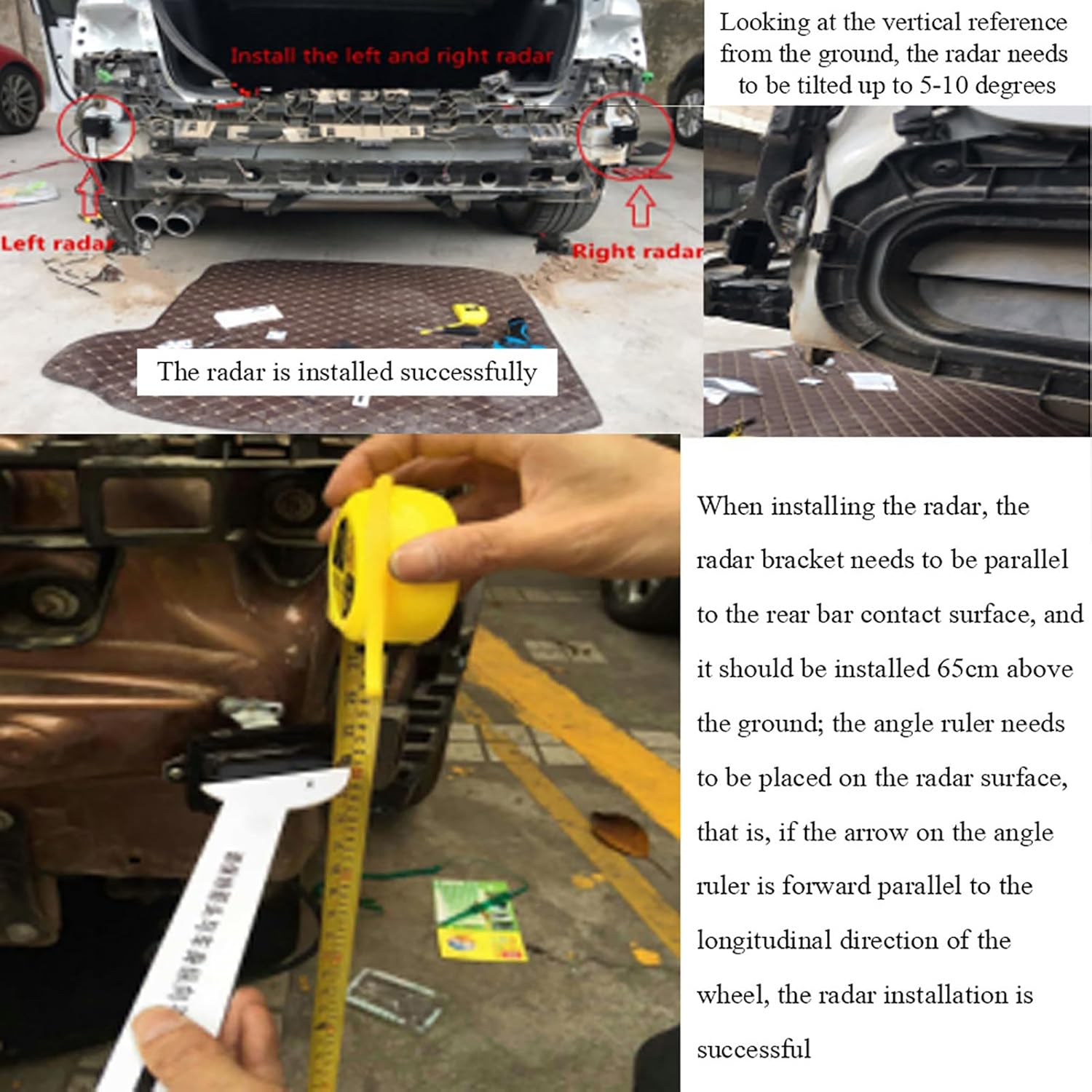
Detailed instructions for radar sensor placement, height, and angle for optimal performance. 
The two radar sensors that detect objects in the blind spot. - Install Notifiers (LED Indicators): Install the two notifiers inside the vehicle, typically near the side mirrors, where they are easily visible to the driver. These provide visual warnings.

The LED notifiers provide visual warnings to the driver. - Connect Wiring Harnesses: Connect the sensors, notifiers, and buzzer to the main control unit using the provided wiring harnesses. Ensure all connections are secure and properly insulated. Refer to the wiring diagram for correct connections.

A simplified wiring diagram showing connections between the main engine, probes, buzzer, and indicator lights. 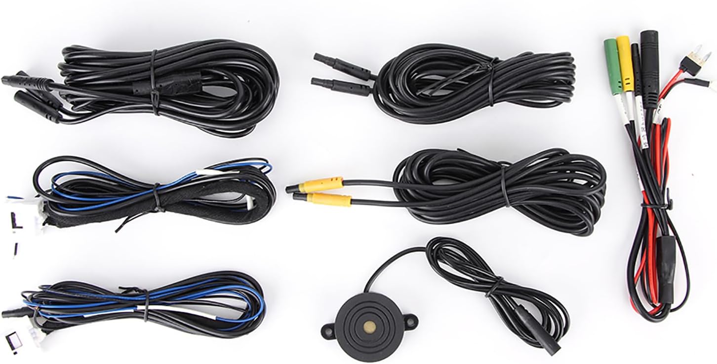
The wiring harnesses and buzzer component. - Test System: Reconnect the vehicle's battery and test the system according to the operating instructions.
5. Operating Instructions
Once installed, the Astibym Blind Spot Detection Monitoring System operates automatically when the vehicle is in motion. It provides a 4-in-1 alert system:
- Blind Spot Detection (BSD): When a vehicle enters your blind spot, the LED notifier on the corresponding side will illuminate.
- Lane Change Assist (LCA): If you activate your turn signal while a vehicle is detected in your blind spot, the LED notifier will flash, and an audible buzzer will sound, warning you not to change lanes.
- Rear Cross Traffic Alert (RCTA): When reversing, the system detects approaching vehicles from the side and provides visual and audible warnings.
- Door Opening Warning: The system can also provide an alert if a vehicle or object is approaching from behind when you are about to open a door.
The system's warning accuracy is 0.1 meters, with a minimum warning reaction time of 0.75 seconds.

6. Maintenance
To ensure optimal performance of your blind spot detection system, follow these general maintenance guidelines:
- Keep the radar sensors located on the rear bumper clean and free from dirt, snow, ice, or debris. Obstructions can interfere with sensor performance.
- Periodically check all wiring connections to ensure they remain secure.
- Avoid using harsh chemicals or abrasive materials when cleaning the sensors or notifiers.
7. Troubleshooting
If you experience issues with your blind spot detection system, consider the following:
- No Power/System Not Activating: Check all power connections and ensure the vehicle's battery is properly connected. Verify fuses if applicable.
- Inaccurate or Intermittent Alerts: Ensure the radar sensors are clean and free from obstructions. Check for proper installation angle and height as described in Section 4. Verify all wiring connections are secure.
- Constant Alerts: This could indicate a sensor obstruction or a wiring issue. Clean sensors and check connections.
- Buzzer Not Sounding/LED Not Lighting: Check the connections to the buzzer and LED notifiers. Ensure they are not damaged.
If problems persist after basic troubleshooting, contact customer support.
8. Specifications
| Feature | Specification |
|---|---|
| Detection Range Accuracy | 0.1 |
| Maximum Detection Range | 15 Meters / 49.2 ft |
| Warning Range | 3-15 Meters / 9.8-49.2 ft |
| System Warning Accuracy | 0.1 M |
| Warning Method | Sound & Light |
| IP Rating | IP67 |
| Warning Time | Minimum reaction time 0.75 sec |
| Rated Current | 130mA ± 50mA |
| Working Voltage | 12V |
| Working Frequency | 24GHz - 24.25GHz |
| Level Angle | Frequency emission 42° x 80° |
| Speed Range | -20m/s to 20m/s (72M) |
| Working Temperature | -45°C to 85°C |
| Item Model Number | Astibymdn67gt1ywk |
| Item Weight | 680 g |
| Parcel Dimensions | 25.2 x 20.19 x 7.19 cm |
9. Warranty Information
Please refer to the product packaging or the retailer's website for specific warranty details. Generally, products are covered against manufacturing defects for a limited period from the date of purchase. Keep your proof of purchase for warranty claims.
10. Customer Support
For technical assistance, troubleshooting beyond this manual, or warranty inquiries, please contact Astibym customer support through the retailer where the product was purchased or visit the official Astibym website for contact information.