1. Introduction
This manual provides essential instructions for the safe and effective operation, setup, and maintenance of your GRAUTOSPOT F3000 Portable Electric Spot Welder Machine. Please read this manual thoroughly before using the device to ensure proper function and to prevent injury or damage.
2. Safety Instructions
WARNING: Welding operations can be hazardous. Always follow safety precautions to prevent electric shock, fire, burns, and other serious injuries. Consult a comprehensive welding safety guide for detailed information.
- Always wear appropriate personal protective equipment (PPE), including welding helmet, gloves, and protective clothing.
- Ensure the work area is well-ventilated and free from flammable materials.
- Do not operate the welder in damp or wet conditions.
- Verify the power supply matches the welder's voltage requirements (110 Volts for this model).
- Disconnect power before performing any maintenance or changing electrodes.
- Keep children and unauthorized personnel away from the welding area.
3. Product Components
The GRAUTOSPOT F3000 spot welder comes with several key components and accessories:
- Main Spot Welder Unit
- Replaceable Welding Electrode Arms (various lengths and shapes)
- Hexagon Key (for adjustments)
- Extra Welding Tips

Figure 3.1: The GRAUTOSPOT F3000 Portable Electric Spot Welder with its standard and additional electrode arms.

Figure 3.2: The spot welder shown with three pairs of high-quality replaceable welding electrode arms, including straight and bent designs.
4. Technical Specifications
Refer to the table below for detailed technical specifications of the F3000 model:

Figure 4.1: Overview of the F3000's dimensions and technical data.
| Specification | Value |
|---|---|
| Model | F3000 |
| Voltage | 110 Volts |
| Power Source | AC |
| Item Weight | 28.9 pounds (13.1 kg) |
| Package Dimensions | 23 x 10.75 x 7 inches (58.4 x 27.3 x 17.8 cm) |
| Maximum Welding Thickness | 0.6+0.6mm to 2+2mm (Up to a combined thickness of 1/8" sheet steel) |
| Included Components | F3000 Portable Electric Spot Welder Machine, Replaceable Welding Electrode Arms, Hexagon Key |
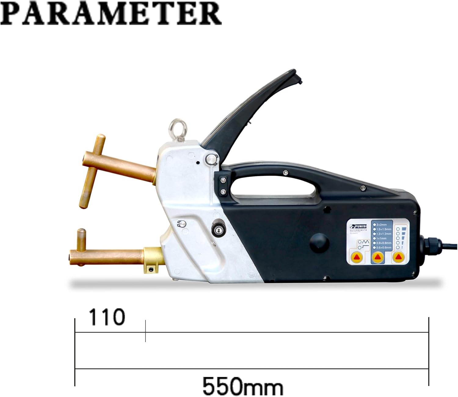
Figure 4.2: The F3000 spot welder indicating its 110 Volt power requirement and approximate length of 550mm.
5. Setup and Assembly
- Unpacking: Carefully remove all components from the packaging. Inspect for any shipping damage.
- Electrode Arm Installation: Select the appropriate welding electrode arms for your task. Insert them into the welder's receptacles and secure them firmly using the provided hexagon key. Ensure the welding tips are clean and properly seated.
- Power Connection: Connect the welder to a grounded 110 Volt AC power outlet. Ensure the circuit can handle the welder's power requirements.
- Workpiece Preparation: Clean the surfaces of the materials to be welded. Remove any rust, paint, oil, or other contaminants that could interfere with the weld.
6. Operation
6.1 Control Panel Overview
The control panel allows you to select welding modes, adjust plate thickness settings, and regulate power output.

Figure 6.1: Diagram of the F3000 control panel, showing controls for welding mode, plate thickness selection, and power regulation.
6.2 Welding Modes
The F3000 offers two primary welding modes:
- Single Point Welding: For standard spot welding applications.
- Pulse Welding: Provides a pulsed current for specific materials or to achieve different weld characteristics.
Use the 'Welding Mode' button on the control panel to toggle between these options.
6.3 Plate Thickness Selection
Select the appropriate thickness setting based on the combined thickness of the materials you are welding. The available settings range from 0.6+0.6mm to 2+2mm.
- 0.6+0.6mm
- 0.8+0.8mm
- 1+1mm
- 1.2+1.2mm
- 1.5+1.5mm
- 2+2mm
Adjust this setting using the 'Plate Thickness Selection' button on the control panel.
6.4 Power Regulation
The 'Power Regulation' control allows fine-tuning of the welding power to achieve optimal results for different materials and thicknesses. Adjust as needed to ensure a strong, consistent weld.
6.5 Welding Arm Adjustment
The welding arm pressure can be adjusted to suit the material and desired weld quality. The adjustable range is typically 40-120KG.

Figure 6.2: Detail showing the welding arm pressure adjustment mechanism and the contact switch for initiating the weld cycle.
6.6 Welding Process
- Select the desired welding mode, plate thickness, and power regulation settings.
- Position the materials to be welded between the electrode arms. Ensure good contact.
- Apply firm pressure to the handle to bring the electrodes into contact with the workpiece.
- Press the contact switch to initiate the welding cycle. The machine will automatically apply current for the set duration.
- Release the handle after the weld is complete. Allow the weld to cool before handling.

Figure 6.3: Example of spot welding on characteristic sheet materials, demonstrating the maximum thickness capability of 2+2mm.

Figure 6.4: Visual representation of a successful spot weld, showing the fused area between two metal pieces.
7. Maintenance
- Electrode Tips: Regularly inspect and clean the welding tips. Replace them when they become worn or pitted to ensure consistent weld quality.
- General Cleaning: Keep the welder clean and free from dust and debris. Use a dry cloth to wipe down the exterior.
- Cable Inspection: Periodically check the power cord and welding cables for any signs of damage, fraying, or exposed wires. Replace damaged cables immediately.
- Storage: Store the welder in a dry, clean environment when not in use.
8. Troubleshooting
This section addresses common issues you might encounter with your spot welder.
- No Weld/Weak Weld:
- Check power connection.
- Ensure workpiece surfaces are clean and free of contaminants.
- Verify correct plate thickness setting.
- Increase power regulation setting.
- Inspect electrode tips for wear; replace if necessary.
- Ensure sufficient pressure is applied to the welding arms.
- Overheating Protection Activated:
- The welder has a built-in overheating protection system. If it activates, allow the machine to cool down before resuming operation.
- Ensure adequate ventilation around the machine.
- Inconsistent Welds:
- Check for loose connections or worn electrode tips.
- Ensure consistent pressure on the welding arms.
- Verify material cleanliness and consistency.
If you encounter issues not covered here or require further assistance, please contact GRAUTOSPOT customer support.
9. Warranty and Support
For information regarding warranty coverage, technical support, or replacement parts, please refer to the documentation included with your purchase or visit the official GRAUTOSPOT website. Contact details for customer service are typically provided in the product packaging.