1. Introduction
This manual provides essential instructions for the safe and effective operation, setup, and maintenance of your CREWORKS Mini Metal Lathe, model YS-2140A. This benchtop machine is designed for precision metalworking tasks, including turning, drilling, and threading on various materials such as wood, plastics, brass, and aluminum.
Before operating the lathe, carefully read and understand all instructions and safety warnings contained within this manual. Retain this manual for future reference.

Figure 1.1: CREWORKS Mini Metal Lathe YS-2140A with various tools and accessories.
2. Safety Instructions
Operating any machinery carries inherent risks. Adhering to safety protocols is crucial to prevent injury and damage to the equipment. Always prioritize safety.
2.1 General Safety
- Read and understand the entire manual before operation.
- Ensure the work area is clean, well-lit, and free from obstructions.
- Keep children and unauthorized personnel away from the machine.
- Do not operate the lathe under the influence of drugs, alcohol, or medication.
- Always wear appropriate personal protective equipment (PPE), including safety glasses, hearing protection, and suitable clothing. Avoid loose clothing, jewelry, and long hair.
2.2 Electrical Safety
- Ensure the power supply matches the machine's requirements.
- Never operate the machine with damaged power cords or plugs.
- Disconnect power before performing any maintenance, adjustments, or when the machine is not in use.
2.3 Operational Safety
- Secure workpieces firmly in the chuck or collet.
- Ensure all guards are in place before starting the machine. The transparent chuck guard protects against swarf and broken tools.
- Never leave the machine unattended while it is running.
- Use the emergency stop button in case of an unexpected event.

Figure 2.1: Power and Emergency Stop controls.
3. Product Overview and Components
The CREWORKS Mini Metal Lathe YS-2140A is a compact yet capable machine for various metalworking applications. Familiarize yourself with its main components for safe and efficient operation.

Figure 3.1: Main components of the CREWORKS Mini Metal Lathe.
Key Components:
- Headstock: Houses the main spindle, chuck, and gear train.
- Chuck: A 3-jaw chuck for holding workpieces.
- Digital Speed Display: Shows the current spindle rotational speed.
- Speed Adjustment: Knob for controlling spindle RPM.
- Forward/Reverse Switch: Controls the direction of spindle rotation.
- Tool Post: Holds cutting tools.
- Carriage: Moves along the bed, carrying the cross slide and tool post. Controlled by the Carriage Handwheel.
- Cross Slide: Moves perpendicular to the bed, controlled by the Cross Slide Handwheel.
- Compound Rest: Rotates and moves along the cross slide, controlled by the Compound Control Wheel, allowing for angled cuts.
- Tailstock: Supports the end of long workpieces or holds drilling/reaming tools. Features a Quill and Tail Feed Handwheel.
- Lead Screw: Engages with the half-nut lever for automatic feeding and threading operations.
- Dual V-Shaped Guide Rails: Provide precise and stable movement for the carriage and tailstock.
- Chuck Guard: Transparent shield for operator safety.
4. Setup
4.1 Unpacking and Inspection
- Carefully remove the lathe from its packaging. It is recommended to have two people for unboxing and placement due to the machine's weight (approximately 134.2 lbs).
- Inspect the machine for any signs of shipping damage. Report any damage to the carrier and seller immediately.
- Remove any protective coatings or excess grease/oil from the machine surfaces using a suitable cleaner.
- Verify all included accessories are present according to the packing list.
4.2 Placement and Mounting
- Place the lathe on a sturdy, level workbench or stand capable of supporting its weight and resisting vibration during operation.
- Securely bolt the lathe to the workbench using appropriate fasteners to prevent movement.
- Ensure adequate clearance around the machine for safe operation and material handling.
4.3 Electrical Connection
- Connect the lathe to a grounded electrical outlet that meets the machine's power requirements (750W motor).
- Do not use extension cords unless absolutely necessary, and ensure they are rated for the machine's power draw.
5. Operating Instructions
5.1 Powering On/Off and Speed Adjustment
- Ensure all safety guards are in place and the workpiece is securely mounted.
- Press the green 'ON' button to power on the machine.
- Adjust the spindle speed using the speed adjustment knob. The current RPM will be displayed on the digital screen. The lathe offers a stepless adjustment from 0 to 2500 RPM.
- Use the Forward/Reverse switch to select the desired rotation direction.
- To turn off, press the red 'OFF' button or the emergency stop button.

Figure 5.1: Digital display for precise speed adjustment.
5.2 Workpiece Clamping (3-Jaw Chuck)
The lathe is equipped with a 5-inch (125 mm) 3-jaw chuck suitable for holding both square and round workpieces.
- Insert the chuck key into the chuck.
- Open the jaws sufficiently to insert the workpiece.
- Place the workpiece firmly against the chuck face.
- Tighten the chuck jaws evenly using the chuck key until the workpiece is securely held. Remove the chuck key before starting the lathe.
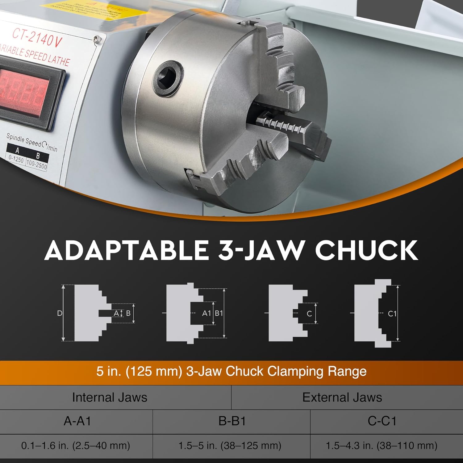
Figure 5.2: Adaptable 3-jaw chuck for securing workpieces.
5.3 Tool Post and Tooling
- Loosen the tool post locking mechanism.
- Insert the cutting tool into the tool holder.
- Adjust the tool height so that the cutting edge is precisely on the centerline of the workpiece. Use shims if necessary.
- Tighten the tool post locking mechanism securely.

Figure 5.3: Tool post for mounting cutting tools.
5.4 Carriage, Cross Slide, and Compound Rest
These components allow for precise control over the cutting tool's position.
- Carriage Handwheel: Moves the entire carriage assembly along the lathe bed (longitudinal feed).
- Cross Slide Handwheel: Moves the cross slide perpendicular to the lathe bed (cross feed).
- Compound Control Wheel: Moves the compound rest, which can be angled for taper turning or chamfering.

Figure 5.4: Handwheels for precise control of machine movements.
5.5 Tailstock Operation
The tailstock is used to support long workpieces or to hold drilling and reaming tools.
- Loosen the tailstock locking lever to slide the tailstock along the bed.
- Position the tailstock as needed and lock it securely.
- Use the Tail Feed Handwheel to extend or retract the tailstock quill.
- The tailstock quill can be locked in position using the Quill Lock.

Figure 5.5: Tailstock quill with measurement markings.
5.6 Threading Operations
The lathe supports both metric (0.5-3 mm) and inch (8-44 tpi) threading. Changing gears is required for different thread pitches.
- Refer to the threading chart on the machine for the correct gear combination for your desired thread pitch.
- Access the gear train cover and replace gears as indicated by the chart.
- Engage the half-nut lever to connect the carriage to the lead screw for automatic feed during threading.

Figure 5.6: Durable metal gear set for power transmission and threading.
6. Maintenance
Regular maintenance ensures the longevity and precision of your CREWORKS Mini Metal Lathe.
6.1 Cleaning
- After each use, clean the machine thoroughly, removing all chips and swarf.
- Wipe down all exposed metal surfaces, especially the bedways, to prevent rust.
6.2 Lubrication
- Regularly lubricate all moving parts, including the lead screw, cross slide, compound rest, and tailstock quill.
- Apply a thin coat of machine oil to the bedways to ensure smooth movement and prevent wear.
6.3 Inspection
- Periodically inspect the drive belts for wear and tension.
- Check all fasteners for tightness and tighten as necessary.
- Examine the chuck jaws for wear or damage.
- Inspect the Dual V-Shaped Guide Rails for any damage or excessive wear.
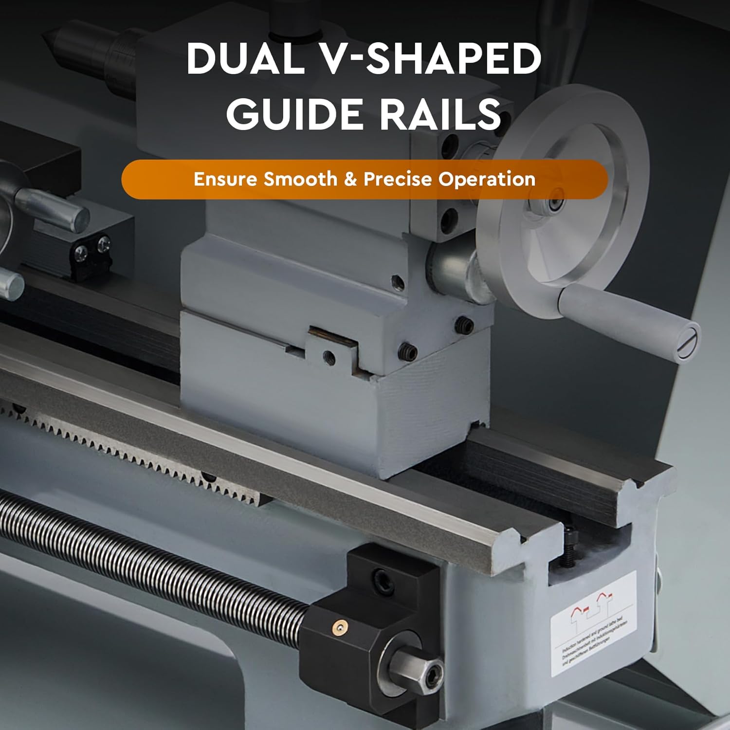
Figure 6.1: Dual V-shaped guide rails for precise movement.
7. Troubleshooting
This section addresses common issues you might encounter during the operation of your lathe. For problems not listed here or for complex repairs, contact CREWORKS customer support.
| Problem | Possible Cause | Solution |
|---|---|---|
| Lathe does not power on | No power supply; Emergency stop engaged; Faulty switch | Check power connection; Disengage emergency stop; Contact support |
| Spindle not rotating | Motor issue; Belt disengaged; Speed set to zero | Check motor connection; Inspect/adjust belt; Increase speed setting |
| Excessive vibration or noise | Unbalanced workpiece; Loose mounting; Worn bearings; Dull cutting tool | Balance workpiece; Tighten mounting bolts; Inspect bearings; Sharpen/replace tool |
| Inaccurate cuts | Loose tool post; Worn slides; Improper tool height; Tailstock misalignment | Tighten tool post; Adjust gibs; Set tool to centerline; Align tailstock |
8. Specifications
Technical specifications for the CREWORKS Mini Metal Lathe YS-2140A.

Figure 8.1: Dimensions and key specifications.
| Feature | Specification |
|---|---|
| Model Number | YS-2140A |
| Product Dimensions | 31.5 x 11.5 x 13.5 inches |
| Item Weight | 134.2 pounds (61 kg) |
| Rated Power | 750W (1 HP) |
| Swing Over Bed | 8.3 inches (210 mm) |
| Distance Between Centers | 15.7 inches (400 mm) |
| Spindle Bore | 1.5 inches (38 mm) |
| Spindle Taper | MT#5 |
| Tailstock Taper | MT#2 |
| Chuck Diameter | 5 inches (125 mm) |
| Max. Spindle Speed | 2500 rpm |
| Metric Thread Range | 0.5-3 mm |
| Inch Thread Range | 8-44 tpi |
| Material | Cast Iron, Stainless Steel, ABS |
9. Warranty and Support
CREWORKS products are designed for durability and performance. For warranty information, product support, or to inquire about replacement parts, please contact CREWORKS directly through their official channels or the retailer where the product was purchased.
Please have your model number (YS-2140A) and purchase details available when contacting support to expedite assistance.


