1. Introduction
This manual provides comprehensive instructions for the safe and effective installation, operation, and maintenance of your new Technology Parts Store Spindle Assembly. This 3-pack spindle assembly is designed as a direct replacement for specific AYP lawn mower models with 44-inch, 46-inch, and 50-inch ventilated decks. Proper installation and maintenance are crucial for optimal performance and longevity of your lawn mower deck.
2. Product Specifications
- Part Numbers: Replaces OEM # for AYP: 137152, 137553, 143651, 532137152, 532137553, 532143651
- Height: 5 inches (127 mm)
- Mounting Hole Distance: 4.84 inches (123 mm)
- Shaft Design: 5-point star shaped center hole
- Bearings: Sealed bearings for extended life
- Included Components: Blade bolt, washers, and mounting bolts

Figure 2.1: Dimensional diagram of the spindle assembly, illustrating height, mounting hole distance, and shaft details.
3. Compatibility
This spindle assembly is compatible with various AYP lawn mower models utilizing 44-inch, 46-inch, and 50-inch ventilated cutting decks. Please verify your original equipment manufacturer (OEM) part number against the listed replacement numbers (137152, 137553, 143651, 532137152, 532137553, 532143651) to ensure proper fitment before installation.
4. Package Contents
Upon opening the package, ensure all the following components are present:
- 3 x Spindle Assemblies
- 3 x Blade Bolts
- Washers (as required for blade attachment)
- Mounting Bolts (for securing spindle to deck)
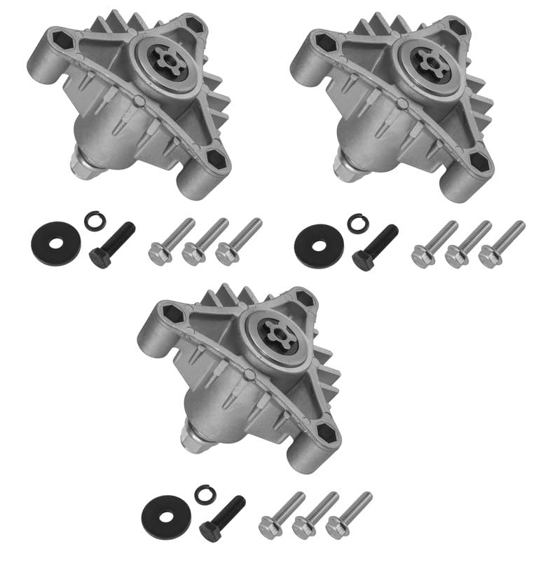
Figure 4.1: View of the three spindle assemblies included in the package.
5. Safety Information
Always prioritize safety when working with power equipment. Failure to follow safety precautions can result in serious injury.
- Disconnect Power: Before performing any maintenance or installation, always disconnect the spark plug wire from the spark plug to prevent accidental engine starting.
- Wear Protective Gear: Use appropriate personal protective equipment (PPE), including safety glasses, gloves, and sturdy footwear.
- Stable Work Area: Ensure the lawn mower is on a flat, stable surface and properly supported to prevent it from tipping.
- Sharp Blades: Mower blades are sharp. Handle them with extreme care and wear heavy-duty gloves.
- Read Manuals: Refer to your lawn mower's owner's manual for specific safety instructions and deck removal procedures.
6. Installation Instructions
Follow these steps carefully to replace the spindle assembly on your AYP lawn mower deck.
- Preparation:
- Park the lawn mower on a level surface.
- Engage the parking brake.
- Disconnect the spark plug wire to prevent accidental starting.
- Lower the cutting deck to its lowest position.
- Remove the cutting deck from the mower according to your mower's owner's manual.
- Clean any grass clippings or debris from the top and bottom of the deck.
- Remove Old Spindle Assembly:
- Carefully remove the mower blade attached to the bottom of the spindle. You may need a block of wood to hold the blade steady while loosening the blade bolt. Note the orientation of the blade.
- Remove the pulley from the top of the spindle shaft.
- Unscrew the mounting bolts that secure the spindle assembly to the deck. These are typically located on the top side of the deck.
- Lift the old spindle assembly off the deck.

Figure 6.1: Top view of the spindle assembly, highlighting the 5-point star shaped center hole for blade attachment.
- Install New Spindle Assembly:
- Position the new spindle assembly onto the deck, aligning the mounting holes.
- Insert the new mounting bolts (included) through the spindle and deck. Tighten them securely, but do not overtighten.
- Reattach the pulley to the top of the spindle shaft.
- Attach the mower blade to the bottom of the spindle shaft, ensuring the blade's cutting edge is facing the correct direction (typically towards the front of the deck). The 5-point star design of the shaft ensures proper blade alignment.
- Secure the blade with the new blade bolt and washers (included). Tighten the blade bolt to the torque specifications recommended in your mower's manual.

Figure 6.2: Side view of the spindle assembly, showing the shaft where the blade and pulley attach.
- Final Steps:
- Reinstall the cutting deck onto the lawn mower.
- Reconnect the spark plug wire.
- Test the mower in a safe, open area to ensure proper operation and no unusual vibrations or noises.
7. Maintenance
Regular maintenance helps extend the life of your spindle assemblies and ensures consistent cutting performance.
- Cleaning: After each use, clean grass clippings and debris from the top and bottom of the deck, especially around the spindle housings. Accumulated debris can cause imbalance and premature wear.
- Inspection: Periodically inspect the spindle assemblies for any signs of damage, excessive wear, or loose bolts. Check for any play in the spindle shaft, which could indicate worn bearings.
- Sealed Bearings: These spindle assemblies feature sealed bearings, which do not require lubrication. Do not attempt to grease or lubricate the bearings, as this can damage the seals.
- Blade Condition: Ensure mower blades are sharp and balanced. Dull or unbalanced blades can put undue stress on the spindle bearings.
8. Troubleshooting
If you encounter issues after installing the new spindle assemblies, consider the following:
- Excessive Vibration:
- Check if blades are properly balanced and sharp.
- Ensure blade bolts are tightened to specification.
- Verify that the spindle mounting bolts are securely fastened.
- Inspect for any debris caught in the deck or around the spindles.
- Unusual Noise (Grinding, Squealing):
- This may indicate bearing failure. While these spindles have sealed bearings, extreme conditions or impacts can cause damage.
- Ensure no foreign objects are interfering with the pulley or blade rotation.
- Poor Cut Quality:
- Confirm blades are sharp and installed with the correct cutting edge orientation.
- Check for excessive play in the spindle shaft, which could affect blade stability.
9. Warranty and Support
For warranty information or technical support regarding your Technology Parts Store Spindle Assembly, please refer to the product packaging or contact Technology Parts Store directly through their official channels. Keep your purchase receipt as proof of purchase.