1. Introduction
This manual provides essential information for the safe and effective installation, operation, and maintenance of the Hilitand NLQ3-125/2P Automatic Transfer Switch (ATS). This device is designed to automatically switch between a normal power supply and a standby power supply, such as a PV inverter or generator, ensuring continuous power for critical loads.
2. Safety Information
Please read all safety warnings and instructions carefully before installing or operating this device. Failure to follow these instructions may result in electric shock, fire, serious injury, or property damage.
- Installation and maintenance should only be performed by qualified electricians.
- Ensure all power sources are disconnected before performing any wiring or maintenance.
- Verify correct voltage and current ratings before connecting the device.
- Do not operate the switch if it appears damaged.
- Always use appropriate personal protective equipment (PPE).
3. Product Overview
The Hilitand NLQ3-125/2P is a 110V 63A 2-pole automatic transfer switch featuring millisecond switching capabilities. It is designed for applications requiring uninterrupted power, such as in homes, shopping malls, factories, laboratories, and farms. The switch ensures continuity, reliability, and safety of the power supply by automatically transferring to a backup source when the normal supply is abnormal.
Key Features:
- Automatic Transfer: Seamlessly switches between normal and standby power supplies.
- Millisecond Switching: Ensures minimal interruption to power supply.
- Durable Construction: Made from flame-retardant PC material and silver alloy contacts for good insulation and aging resistance.
- Wide Application: Suitable for various environments requiring continuous power.
- Isolation and Interference Resistant: Designed for reliable performance.
Product Components:

Figure 3.1: Front view of the Hilitand NLQ3-125/2P Automatic Transfer Switch, showing input/output terminals, manual/auto selector, and power indicators.
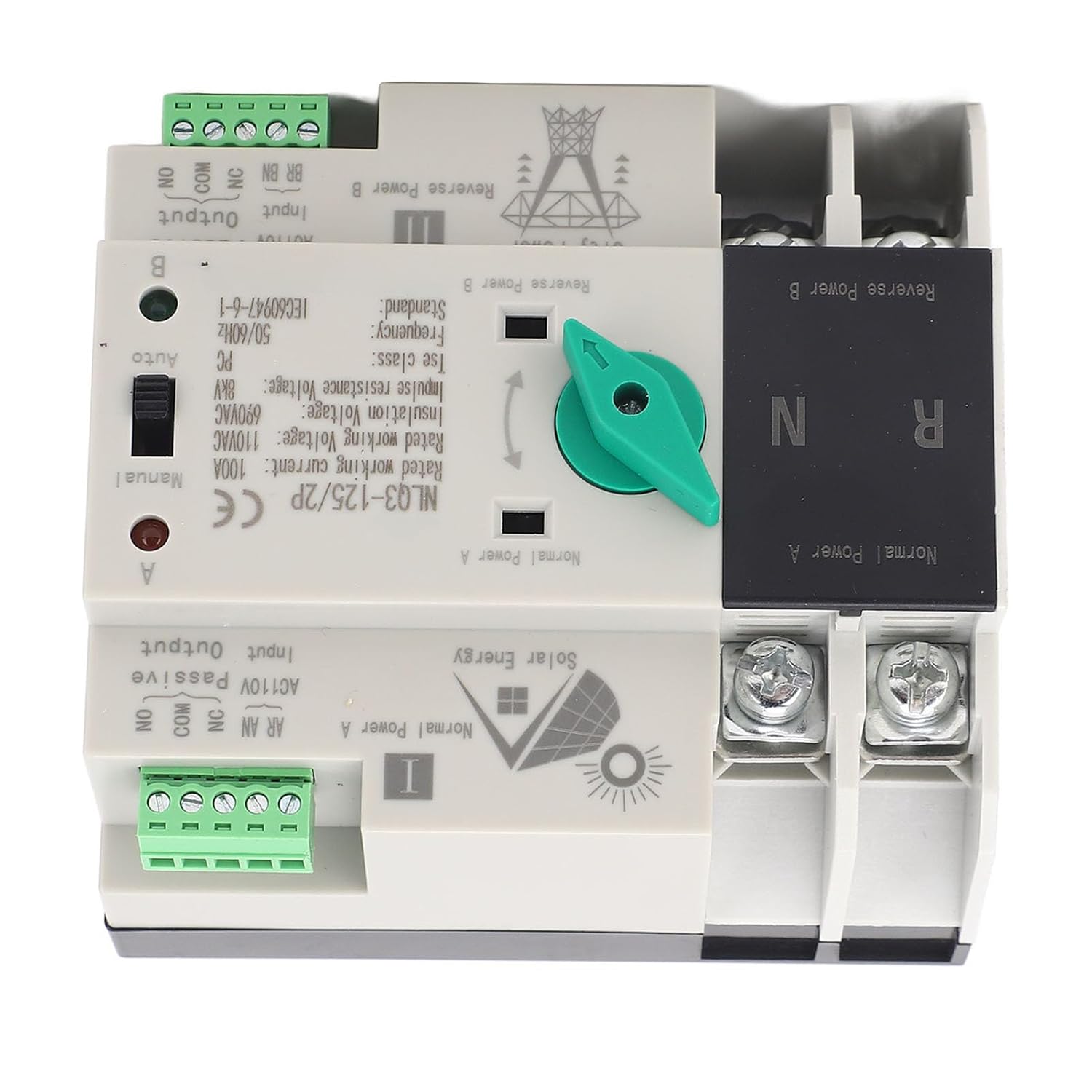
Figure 3.2: Top view of the Automatic Transfer Switch, highlighting the 'Normal Power A' and 'Reverse Power B' sections, along with the manual/auto switch and terminal connections.
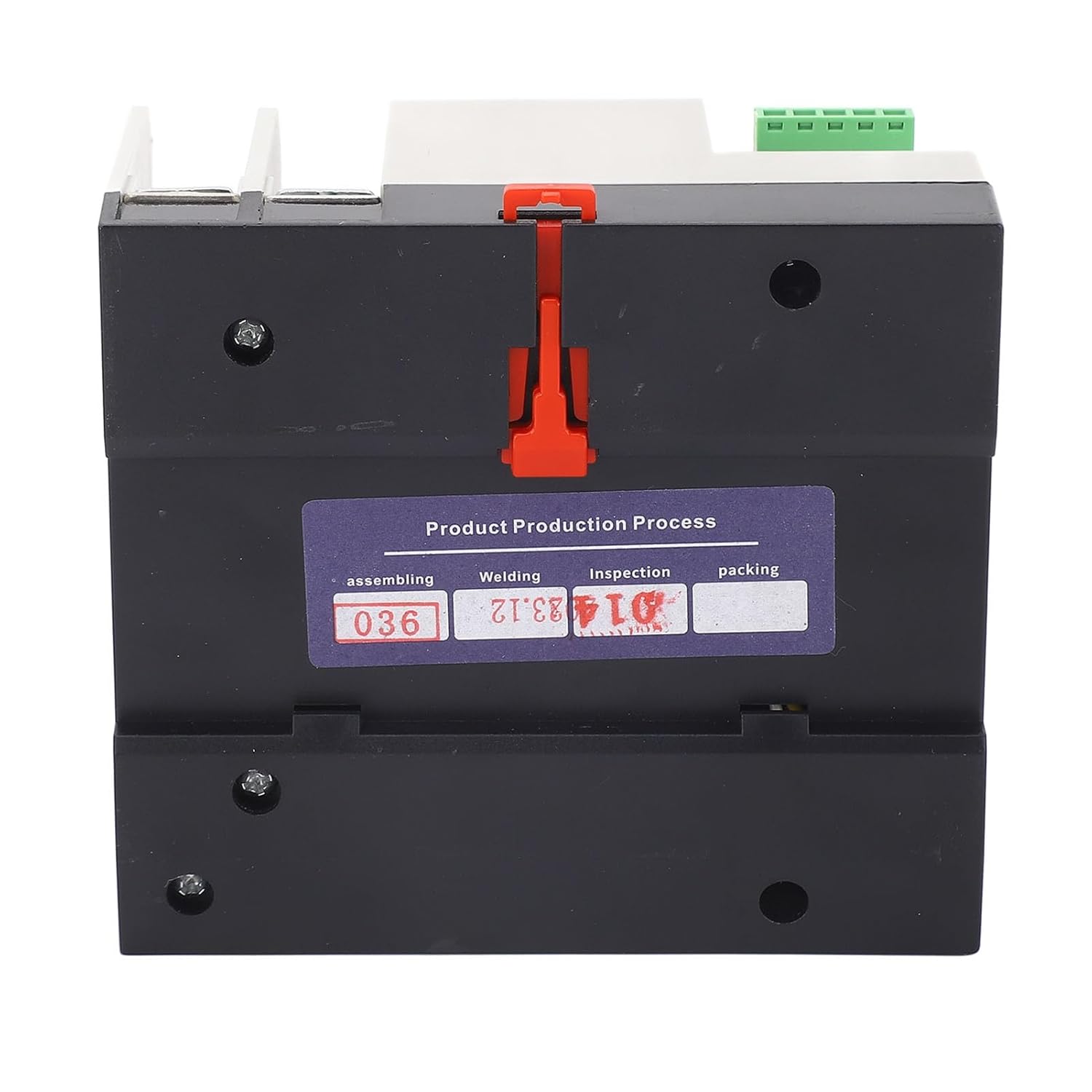
Figure 3.3: Bottom view of the Automatic Transfer Switch, showing the base and a production process label.
4. Specifications
| Parameter | Value |
|---|---|
| Product Model | NLQ3-125/2P |
| Item Type | Dual Power Automatic Transfer Switch |
| Material | Flame Retardant PC, Silver Alloy |
| Switch Type | Secondary Distribution |
| Rated Current | 63A |
| Coil Voltage | 110V AC |
| Insulation Voltage | AC690V AC |
| Rated Voltage | AC400V AC (Note: Product title states 110V, please verify application voltage) |
| Rated Frequency | 50/60Hz |
| Electrical Level | PC Isolation Type |
| Rated Impulse Withstand Voltage | 8KV |
| Control Circuit Rated Control Voltage Us | AC110V 85% Us-110% Us |
| Auxiliary Circuit | 2 Relays, each with 2 sets of contacts capacity: AC110V50HZ le=5y |
| Parcel Dimensions | 11 x 10 x 8 cm |
| Weight | 606 g |

Figure 4.1: Dimensions of the Hilitand NLQ3-125/2P Automatic Transfer Switch, showing approximate measurements of 109mm (4.3in) length, 97mm (3.8in) width, and 69mm (2.7in) height.
5. Setup and Installation
Proper installation is crucial for the safe and reliable operation of the ATS. Refer to the wiring diagram and follow local electrical codes.
Pre-Installation Check:
- Before installation, carefully inspect the integrity of the ATS for any physical damage.
- Use the operating handle to manually open or close the ATS. Check the flexibility of the internal transmission device.
- Test the generation and disconnection conditions of the load for both the normal and standby power supply in each phase to ensure proper functionality before final wiring.
Wiring Diagram:

Figure 5.1: Wiring diagram for the Automatic Transfer Switch. It illustrates connections for Common Feed, Common Control Line, Back-up Line, Stand-by Control Line, and Load Output for both Normal Power A (Solar Energy) and Reverse Power B (City Power).
Installation Steps:
- Mount the ATS securely in a suitable enclosure, ensuring adequate ventilation and clearance.
- Connect the normal power supply (e.g., grid power) to the designated 'Normal Power A' input terminals.
- Connect the standby power supply (e.g., PV inverter or generator) to the designated 'Reverse Power B' input terminals.
- Connect the load to the output terminals of the ATS.
- Connect the control lines as per the wiring diagram. Ensure all connections are tight and secure.
- Double-check all wiring for correctness and adherence to safety standards before applying power.
6. Operating Instructions
The NLQ3-125/2P ATS can operate in both automatic and manual modes.
Automatic Mode:
- Set the selector switch on the device to 'Auto'.
- In this mode, the ATS will automatically monitor the normal power supply.
- If the normal power supply fails or falls outside acceptable parameters, the ATS will automatically switch the load to the standby power supply within milliseconds.
- When the normal power supply is restored, the ATS will automatically transfer the load back to the normal power supply.
Manual Mode:
- Set the selector switch on the device to 'Manual'.
- In manual mode, the user can use the operating handle to switch between 'Normal Power A' and 'Reverse Power B' as needed.
- This mode is typically used for testing, maintenance, or in situations where automatic transfer is not desired.
Application Examples:

Figure 6.1: Visual examples of environments where the ATS can be applied, including household electricity, shopping malls, company offices, and factories, demonstrating its versatility.

Figure 6.2: Another illustration of the ATS's broad applicability, showing it in contexts such as factories, shopping malls, nurseries, and residential buildings with solar panels, emphasizing its use where continuous power is critical.

Figure 6.3: The Automatic Transfer Switch positioned within an industrial manufacturing environment, highlighting its suitability for robust and demanding operational settings.
7. Maintenance
Regular maintenance helps ensure the longevity and reliable operation of your ATS.
- Periodic Inspection: Regularly inspect the ATS for any signs of wear, damage, or loose connections.
- Cleaning: Keep the device clean and free from dust and debris. Use a dry, soft cloth for cleaning. Do not use liquid cleaners.
- Terminal Check: Periodically check all terminal connections to ensure they are tight and secure. Loose connections can lead to overheating and potential failure.
- Functional Test: Conduct periodic functional tests (in manual mode, if safe to do so) to ensure the switching mechanism operates smoothly.
- Professional Service: For any complex issues or internal inspections, consult a qualified electrician.
8. Troubleshooting
If you encounter issues with your ATS, refer to the following common problems and solutions:
| Problem | Possible Cause | Solution |
|---|---|---|
| ATS does not switch automatically | 1. Selector switch in 'Manual' mode. 2. No power detected on standby source. 3. Control circuit fault. | 1. Set selector switch to 'Auto'. 2. Verify standby power source is active. 3. Consult a qualified electrician. |
| No power output | 1. Both normal and standby power sources are off. 2. Loose wiring connections. 3. Internal fault. | 1. Check both power sources. 2. Inspect and tighten all wiring connections (with power off). 3. Consult a qualified electrician. |
| Overheating of terminals | 1. Loose connections. 2. Overload. 3. Incorrect wire gauge. | 1. Tighten all terminal screws (with power off). 2. Reduce load or verify load is within rated capacity. 3. Ensure appropriate wire gauge is used for the current rating. |
For issues not listed above or if solutions do not resolve the problem, contact customer support or a qualified electrician.
9. Warranty and Support
Warranty Information:
This Hilitand product comes with a manufacturer warranty for 90 days from the date of purchase. This warranty covers defects in materials and workmanship under normal use. It does not cover damage caused by improper installation, misuse, accidents, or unauthorized modifications.
Customer Support:
For technical assistance, warranty claims, or further inquiries, please contact Hilitand customer support through your retailer or the official Hilitand channels. Please have your product model number (NLQ3-125/2P) and purchase details ready when contacting support.