1. Introduction
Thank you for choosing the Generic V520 OBD2 Scanner Diagnostic Tool. This manual provides detailed instructions for the proper use, maintenance, and troubleshooting of your device. The V520 is designed to assist in diagnosing vehicle issues by reading and clearing diagnostic trouble codes (DTCs), monitoring vehicle performance data, and checking emission readiness status for all OBDII compliant vehicles.
Please read this manual thoroughly before operating the device to ensure safe and effective use.
2. Product Overview
The V520 OBD2 Scanner is a versatile diagnostic tool featuring a 2.8-inch color screen and an intuitive interface. It supports a wide range of diagnostic functions to help you understand and resolve common vehicle issues.

Figure 2.1: Generic V520 OBD2 Scanner Diagnostic Tool. The device features a color screen, navigation buttons, and an integrated OBDII connector cable.
Key Features:
- Multi-function Testing: Includes engine fault diagnosis, fault clearing, freeze frame data, I/M readiness status, vehicle information reading, real-time data streaming, and battery voltage reading.
- Oxygen Sensor Test & Mode 6/8 Detection: Advanced diagnostic capabilities for specific component monitoring.
- Extensive Fault Code Library: Access to a database of 35,901 Diagnostic Trouble Codes (DTCs) for quick reference.
- User-Friendly Interface: Simple operation with a 2.8-inch color screen and clearly labeled buttons.
- Cloud Printing Function: Ability to generate and potentially print diagnostic reports (requires external setup, refer to device for details).
- Multi-language Support: Supports 10 languages including English, German, French, Spanish, Italian, Russian, Dutch, Chinese, Japanese, and Portuguese.

Figure 2.2: Overview of the V520's main diagnostic functions displayed on the device screen.
Device Components:

Figure 2.3: Labeled diagram of the V520 OBD2 Scanner, highlighting the 2.8-inch color screen, universal OBD connector, fault code shortcut key (DTC), I/M status button, battery voltage button (BAT), navigation keys (up, down, left, right), EXIT button, and OK button.
- 2.8-inch Color Screen: Displays diagnostic information.
- Universal OBD Connector: Connects to the vehicle's OBDII port.
- DTC Button: Shortcut for Diagnostic Trouble Codes.
- I/M Button: Shortcut for I/M Readiness status.
- BAT Button: Shortcut for Battery Voltage reading.
- Navigation Keys: Up, Down, Left, Right for menu navigation.
- EXIT Button: Returns to the previous menu or exits a function.
- OK Button: Confirms selections or enters a function.
3. Setup
3.1 Initial Inspection
Before first use, inspect the V520 scanner for any visible damage. Ensure the OBDII connector cable is securely attached and free from kinks or cuts.
3.2 Connecting to Your Vehicle
- Locate the vehicle's 16-pin Data Link Connector (DLC). This is typically located under the dashboard on the driver's side. Refer to your vehicle's owner's manual if you cannot find it.
- Ensure the vehicle's ignition is in the OFF position.
- Plug the V520 scanner's OBDII connector firmly into the vehicle's DLC.
- Turn the vehicle's ignition to the ON position (engine off). The scanner will power on automatically.
Note: The V520 scanner draws power directly from the vehicle's OBDII port. No external power source is required for basic operation.
4. Operating Instructions
Once connected and powered on, the V520 scanner will display the main menu. Use the navigation keys (Up, Down, Left, Right) to scroll through options and the OK button to select. The EXIT button will take you back to the previous screen.
4.1 Reading and Clearing Diagnostic Trouble Codes (DTCs)
- From the main menu, select "Read Codes" or press the DTC shortcut button. The scanner will communicate with the vehicle's ECU and display any stored DTCs.
- Each DTC will have a code (e.g., P0301) and a brief description. Use the navigation keys to scroll through multiple codes if present.
- To clear codes, select "Clear Codes" from the menu or press the DTC button again (if available as a secondary function). Confirm the action when prompted.
- Important: Clearing codes will turn off the Check Engine Light (CEL) but will not fix the underlying problem. Address the cause of the DTC before clearing to prevent recurrence.
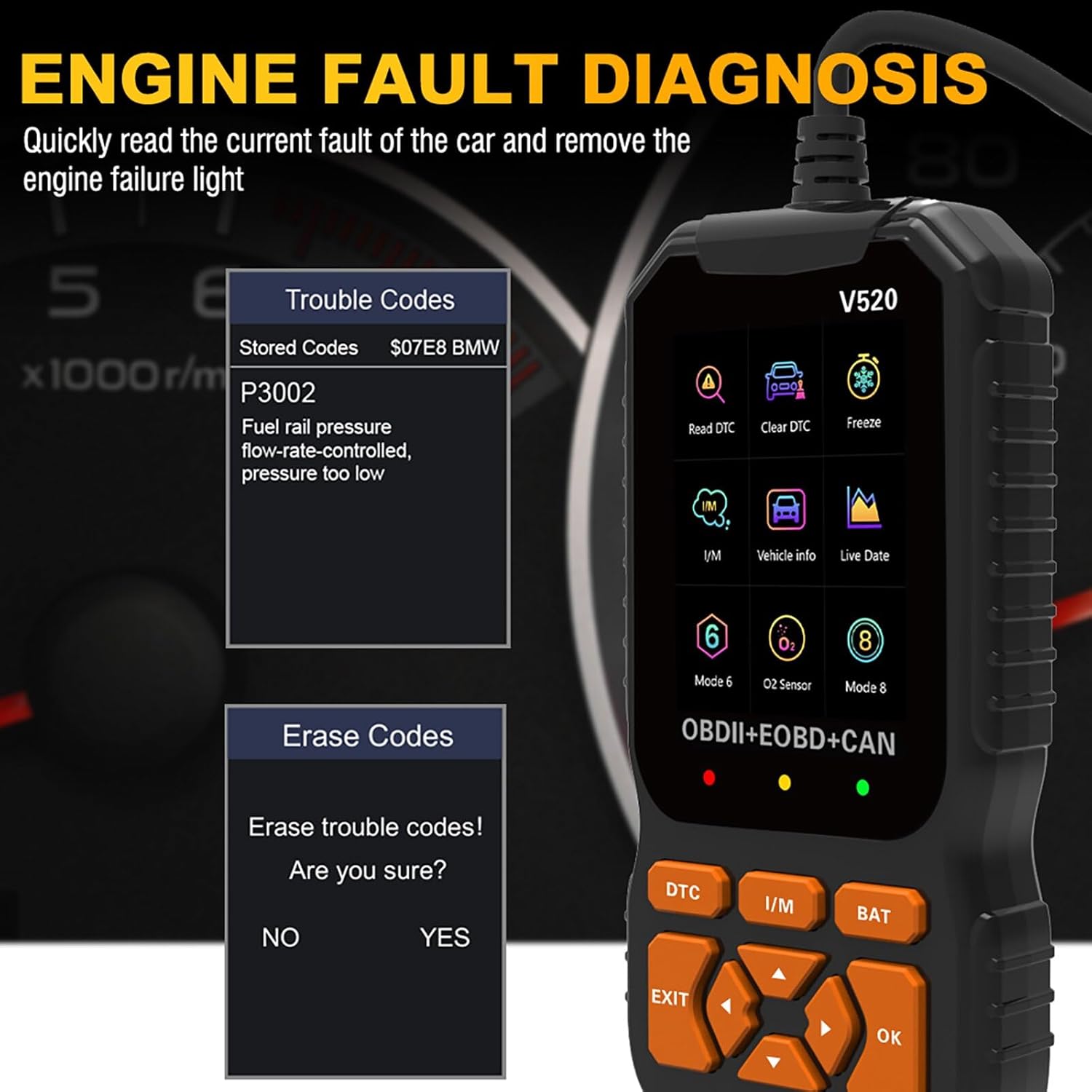
Figure 4.1: Screen display showing options for reading and clearing trouble codes, along with an example of a stored code (P3002).
4.2 Viewing Live Data Stream
This function allows you to view real-time operational parameters of the vehicle's engine and other systems.
- From the main menu, select "Live Data" or "Data Stream".
- A list of available data parameters will be displayed. Select the parameters you wish to monitor.
- The scanner will show the values in real-time, which can be useful for diagnosing intermittent issues or verifying sensor operation.
4.3 I/M Readiness Status
The I/M Readiness function checks if the various emissions-related systems on the vehicle are operating correctly and have completed their self-tests. This is crucial for emissions inspections.
- Press the I/M shortcut button or select "I/M Readiness" from the menu.
- The screen will display the status of various monitors (e.g., MIL, MIS, FUE, CCM, CAT, O2S, EVAP, AIR, HRT, EGR). A "✓" indicates the monitor has completed its test, while an "X" indicates it has not.

Figure 4.2: Screen showing I/M Readiness status, Vehicle Information, Freeze Frame data, On-board Monitor test results, and System Setup options.
4.4 Freeze Frame Data
When an emission-related fault occurs, the vehicle's computer stores certain sensor values at the moment the fault was detected. This "freeze frame" data can help pinpoint the conditions under which the fault occurred.
- From the main menu, select "Freeze Frame".
- The scanner will display various parameters (e.g., engine RPM, vehicle speed, coolant temperature) recorded at the time of the fault.
4.5 Vehicle Information
This function retrieves the Vehicle Identification Number (VIN), Calibration ID (CALID), and Calibration Verification Number (CVN) from the vehicle's ECU.
- From the main menu, select "Vehicle Info".
- The requested information will be displayed on the screen.
4.6 Battery Voltage Reading
Quickly check the vehicle's battery voltage.
- Press the BAT shortcut button or select "Voltage" from the menu.
- The current battery voltage will be displayed.
4.7 Fault Code Lookup (DTC Library)
The V520 includes an extensive built-in library of 35,901 Diagnostic Trouble Codes (DTCs) to help you understand the meaning of codes retrieved from your vehicle.
- From the main menu, select "DTC Lib" or "Fault Code Query".
- Enter the DTC code using the navigation buttons.
- The scanner will display the definition of the code.
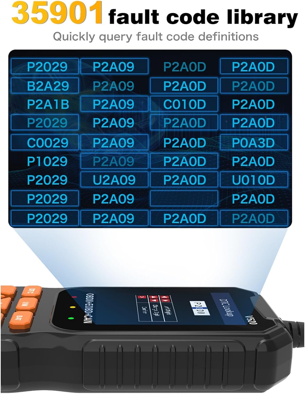
Figure 4.3: Screen displaying a portion of the 35,901 fault code library, allowing users to quickly query fault code definitions.
4.8 Cloud Printing Function
The V520 offers a cloud printing feature to generate diagnostic reports. This typically involves scanning a QR code displayed on the device screen with a smartphone or tablet to access the report for printing or sharing.
- From the main menu, select "Cloud Print".
- Follow the on-screen instructions, which usually involve scanning a QR code with a compatible device.
- The diagnostic report can then be viewed, saved, or printed from your connected device.

Figure 4.4: Screen showing the "Cloud Print" option and an example of a diagnostic report being generated for printing.
5. Maintenance
5.1 Cleaning the Device
To clean the V520 scanner, use a soft, damp cloth. Do not use abrasive cleaners or solvents, as these can damage the screen or casing. Ensure the device is disconnected from any power source before cleaning.
5.2 Storage
Store the device in a clean, dry environment, away from direct sunlight and extreme temperatures. The recommended storage temperature is -30°C to 70°C (-22°F to 158°F). Keep the OBDII connector free from dust and debris.
5.3 Software Updates
Periodically check the manufacturer's website for any available software updates for the V520 scanner. Updates may include bug fixes, new features, or expanded vehicle compatibility. Follow the instructions provided with the update package carefully.
6. Troubleshooting
| Problem | Possible Cause | Solution |
|---|---|---|
| Scanner does not power on. |
|
|
| "Link Error" or "Communication Error" message. |
|
|
| Cannot clear DTCs. |
|
|
7. Specifications

Figure 7.1: Detailed technical specifications for the V520 OBD2 Scanner.
| Parameter | Value |
|---|---|
| Product Model | V520 |
| Operating Voltage | 9-16V |
| Operating Environment Temperature | -30°C to 70°C (-22°F to 158°F) |
| Storage Temperature | -30°C to 70°C (-22°F to 158°F) |
| Product Dimensions (L x W x H) | 171 x 85 x 28 mm (6.73 x 3.35 x 1.1 inches) |
| Item Weight | Approximately 11 ounces (304g with packaging) |
| Communication Interface | Standard OBDII Interface |
| Supported Languages | English, German, French, Spain, Italy, Russia, Netherlands, China, Japan, Portugal |
| Applicable Models | All OBD II Compliant Models (US vehicles 1996 and newer, EU vehicles 2001/2004 and newer) |
| Supported Communication Protocols |
|
8. Warranty and Support
For warranty information and technical support, please refer to the documentation included with your purchase or contact the retailer/manufacturer directly. Keep your purchase receipt as proof of purchase for warranty claims.
If you encounter any issues not covered in this manual, please reach out to customer support for assistance.