1. Introduction
This manual provides detailed instructions for the safe and effective operation of your VIHELM ZT-702S Color Screen Handheld Digital Oscilloscope Multimeter. This device integrates the functions of a digital oscilloscope and a multimeter, offering a versatile tool for electrical measurement and waveform analysis. Please read this manual thoroughly before use and retain it for future reference.
2. Safety Information
Always adhere to the following safety precautions to prevent personal injury and damage to the instrument:
- Electrical Shock Hazard: Do not use the device if it appears damaged or if the test leads are compromised.
- Voltage Limits: Never apply voltage or current that exceeds the specified maximum ratings for the device or its input terminals. Refer to the specifications section for details.
- Proper Terminal Use: Ensure test leads are connected to the correct input terminals for the selected measurement function.
- Fuse Protection: The device is protected by internal fuses. If a fuse blows, replace it only with a fuse of the specified type and rating.
- Battery Safety: Use only the specified battery type (18650). Do not short-circuit, disassemble, or expose batteries to high temperatures.
- Environmental Conditions: Do not operate the device in wet environments or in the presence of explosive gases or vapors.
- Servicing: Refer all servicing to qualified personnel. Do not attempt to repair the device yourself.
3. Package Contents
Verify that all items listed below are present in your package:
- ZT-702S Digital Oscilloscope Multimeter (x1)
- Test Leads (x1 pair)
- Oscilloscope Probe (x1)
- Thermocouple (x1)
- Carrying Case (x1)
- Screwdriver (x1)
- USB Charging Cable (x1)
- User's Manual (x1)
4. Product Overview
The VIHELM ZT-702S combines a digital oscilloscope and a full-featured multimeter in a compact, handheld design. It features a color screen for clear display of waveforms and measurement data.
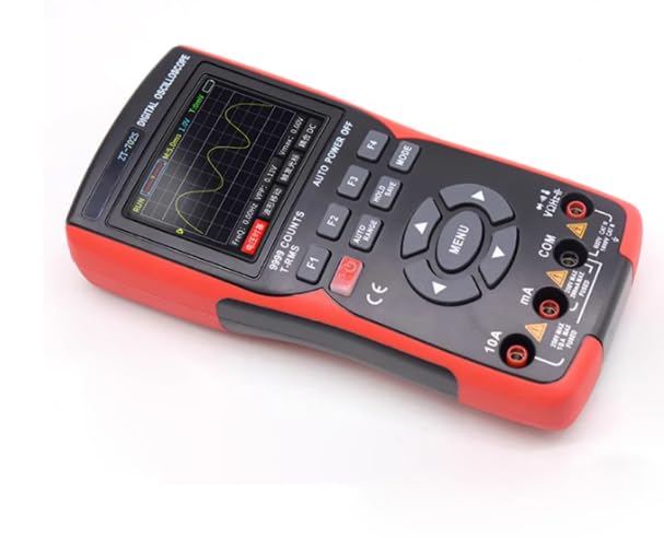
Figure 4.1: Front view of the ZT-702S Digital Oscilloscope Multimeter, showing the color display, function buttons, navigation keys, and input terminals.
The device's interface includes a 2.8-inch color screen, dedicated function buttons (F1-F4), navigation keys, a 'MENU' button for mode selection, and input terminals for various measurements.
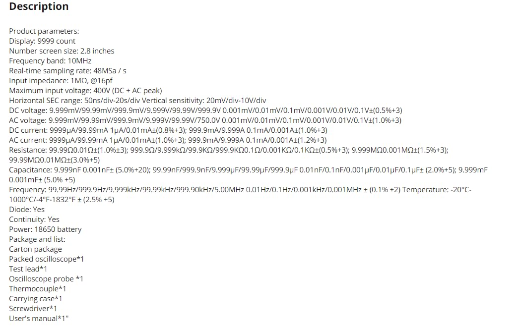
Figure 4.2: The ZT-702S device displayed alongside its complete set of accessories, including test leads, oscilloscope probe, thermocouple, USB cable, and carrying case.
The rear of the device features a kickstand for convenient desktop use and a battery compartment. A caution label regarding fuse replacement is also present.
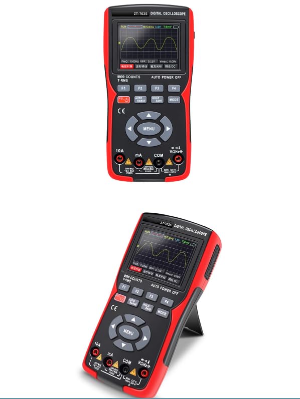
Figure 4.3: Rear view of the ZT-702S, highlighting the integrated kickstand for hands-free operation and the safety warning regarding fuse installation.
5. Setup
5.1 Battery Installation
- Ensure the device is powered off.
- Locate the battery compartment on the rear of the device.
- Use the provided screwdriver to open the battery compartment cover.
- Insert the 18650 battery, observing correct polarity (+/-).
- Securely close the battery compartment cover.
5.2 Charging the Battery
Connect the USB charging cable to the device's charging port and to a standard USB power adapter (not included). The charging indicator will show the charging status. Ensure the device is fully charged before first use for optimal battery life.
5.3 Connecting Test Leads/Probes
For multimeter functions, insert the red test lead into the VΩHz+ terminal and the black test lead into the COM terminal. For current measurements, use the 10A or mA terminals as appropriate. For oscilloscope functions, connect the oscilloscope probe to the dedicated BNC connector (if applicable) or use the test leads with appropriate adapters.
6. Operating Instructions
6.1 Power On/Off
Press and hold the red power button (usually labeled with a power symbol) to turn the device on or off.
6.2 Mode Selection
Press the 'MENU' button to cycle through the main operating modes: Oscilloscope Mode and Multimeter Mode. Use the navigation keys to select specific functions within each mode.
6.3 Oscilloscope Mode
In Oscilloscope Mode, the device displays real-time waveforms. Key parameters such as frequency (F:FREQ), peak-to-peak voltage (VPP), and maximum voltage (Vmax) are shown on the screen.
- Horizontal Control: Use the navigation keys or dedicated buttons (e.g., F1/F2) to adjust the time base (horizontal scale).
- Vertical Control: Use the navigation keys or dedicated buttons (e.g., F3/F4) to adjust the vertical sensitivity (voltage scale).
- Triggering: The device typically features auto-triggering. Manual trigger adjustments may be available via menu options.
- Auto Range/Auto Set: Press the 'AUTO RANGE' button to automatically adjust the horizontal and vertical scales for an optimal waveform display.
- Hold/Save: Use the 'HOLD' button to freeze the current waveform on the screen. The 'SAVE' function allows storing waveform data.
6.4 Multimeter Mode
In Multimeter Mode, the device performs various electrical measurements. Use the 'MODE' button or navigation keys to select the desired function.
- DC Voltage (VDC): Connect test leads in parallel with the DC voltage source.
- AC Voltage (VAC): Connect test leads in parallel with the AC voltage source.
- DC Current (ADC): Connect test leads in series with the circuit. Ensure correct terminal selection (mA or 10A).
- AC Current (AAC): Connect test leads in series with the circuit. Ensure correct terminal selection (mA or 10A).
- Resistance (Ω): Connect test leads across the component to measure resistance. Ensure the circuit is de-energized.
- Capacitance (F): Connect test leads across the capacitor. Ensure the capacitor is discharged before measurement.
- Frequency (Hz): Connect test leads to the signal source.
- Diode Test: Connect test leads across the diode. The display will show the forward voltage drop.
- Continuity Test: Connect test leads across the circuit or component. An audible beep indicates continuity.
- Temperature Measurement (°C/°F): Connect the thermocouple to the device and place the probe tip on the object to be measured.
7. Maintenance
7.1 Cleaning
Wipe the device with a soft, damp cloth. Do not use abrasive cleaners or solvents. Ensure the device is powered off and disconnected from any power source before cleaning.
7.2 Battery Care
If the device will not be used for an extended period, remove the battery to prevent leakage. Recharge the battery regularly to maintain its health, even if not in use.
7.3 Fuse Replacement
If the current measurement function fails, the fuse may need replacement. Refer to the specifications for the correct fuse type and rating. Always disconnect power and test leads before opening the device to replace fuses.
7.4 Storage
Store the device in its carrying case in a cool, dry place, away from direct sunlight and extreme temperatures.
8. Troubleshooting
- Device does not power on: Check battery charge level and ensure the battery is correctly installed.
- No reading in Multimeter Mode: Verify test lead connections, ensure the correct function is selected, and check if the circuit is live (for voltage/current) or de-energized (for resistance/capacitance).
- Distorted waveform in Oscilloscope Mode: Adjust the horizontal (time base) and vertical (voltage sensitivity) scales. Ensure the probe is correctly connected and compensated.
- Inaccurate readings: Check battery level. Ensure test leads are not damaged. Perform a self-calibration if available (refer to device menu).
- Fuse blown for current measurement: Replace the fuse with the specified type and rating.
9. Specifications
| Parameter | Value |
|---|---|
| Display | 9999 Counts, 2.8-inch Color Screen |
| Oscilloscope Bandwidth | 10MHz |
| Real-time Sampling Rate | 48MSa/s |
| Input Impedance | 1MΩ @16pF |
| Maximum Input Voltage | 400V (DC + AC peak) |
| Horizontal SEC Range | 50ns/div - 20s/div |
| Vertical Sensitivity | 20mV/div - 10V/div |
| DC Voltage Range | 9.999mV / 99.99mV / 999.9mV / 9.999V / 99.99V / 999.9V (0.5%+3) |
| AC Voltage Range | 9.999mV / 99.99mV / 999.9mV / 9.999V / 99.99V / 750.0V (1.0%+3) |
| DC Current Range | 9.999μA / 99.99mA / 1.0A (0.8%+3); 9.999mA / 9.999A (1.2%+3) |
| AC Current Range | 9.999μA / 99.99mA / 1.0A (1.0%+3); 9.999mA / 9.999A (1.2%+3) |
| Resistance Range | 99.99Ω / 999.9Ω / 9.999kΩ / 99.99kΩ / 999.9kΩ (0.5%+3); 9.999MΩ / 99.99MΩ (1.5%+3) |
| Capacitance Range | 9.999nF (5.0%+20); 99.99nF / 999.9nF / 9.999μF / 99.99μF / 999.9μF (2.0%+5); 9.999mF (5.0%+5) |
| Frequency Range | 99.99Hz / 999.9Hz / 9.999kHz / 99.99kHz / 999.9kHz / 5.00MHz (0.1%+2) |
| Temperature Range | -20°C - 1000°C / -4°F - 1832°F (2.5%+5) |
| Diode Test | Yes |
| Continuity Test | Yes |
| Power Source | 18650 Battery |
| Dimensions (approx.) | 177mm x 89mm x 40mm |
10. Warranty and Support
The VIHELM ZT-702S Digital Oscilloscope Multimeter is covered by a manufacturer's warranty against defects in materials and workmanship. For specific warranty terms, duration, and to obtain technical support or service, please refer to the warranty card included with your product or contact the manufacturer directly through their official support channels. Keep your purchase receipt as proof of purchase.