
1. Introduction
The ESSISH DT830B is a compact, handheld digital multimeter designed for measuring AC/DC voltage, DC current, resistance, diode forward voltage drop, and transistor hFE. It is suitable for hobbyists, DIY enthusiasts, and general electrical testing applications. This manual provides essential information for safe and effective operation of the device.
Key Features:
- 13/12 digits, 7-segment, 0.5" high LCD Display.
- Max display: 1999, with auto polarity indication.
- Sampling rate: 2-3 readings per second.
- Diode assembly test and Transistor hFE test functions.
- Low battery voltage indication.
2. Safety Information
To ensure safe operation and avoid damage to the meter, please read and follow all safety instructions carefully. This device is designed for high safety, but improper use can still lead to hazards.
- Always ensure the meter is set to the correct range and function before making any measurements.
- Never apply voltage to the meter when the rotary switch is set to Resistance, Diode, or hFE function.
- Never exceed the maximum input values for any range:
- Max DC Voltage: 1000V
- Max AC Voltage: 750V
- Max DC Current: 10A (unfused)
- Exercise extreme caution when working with voltages above 60V DC or 30V AC RMS, as these pose a shock hazard.
- Disconnect the test leads from the circuit before changing functions or ranges.
- Do not use the meter if it appears damaged or if the test leads are damaged.
- Replace the battery when the low battery indicator appears to ensure accurate readings.
- Keep hands and fingers behind the probe barriers during measurements.
3. Product Overview
The DT830B Digital Multimeter consists of a main unit and a pair of test leads. Familiarize yourself with the components before operation.

Figure 3.1: Front view of the ESSISH DT830B Digital Multimeter with connected test leads. This image shows the LCD display, rotary switch, input jacks, and the red and black test probes.
3.1. Components
- LCD Display: Shows measurement readings, units, and other indicators like "HV" for high voltage.
- Rotary Switch: Used to select the desired measurement function and range.
- Input Jacks:
- "VΩmA" Jack: Positive input for voltage, resistance, and current measurements (up to 200mA).
- "10ADC" Jack: Positive input for high current DC measurements (up to 10A). This input is unfused.
- "COM" Jack: Common (negative) input for all measurements.
- hFE Socket: For testing NPN and PNP transistors.
- Test Leads: Red (positive) and Black (negative) leads with probes for connecting to circuits.

Figure 3.2: Close-up view of the red and black test leads, showing the insulated handles and metal probe tips. These leads are essential for making electrical connections.
4. Setup
4.1. Battery Installation
The DT830B requires a 9V battery (not included). To install or replace the battery:
- Ensure the multimeter is turned OFF.
- Locate the battery compartment cover on the back of the meter.
- Remove the screw(s) securing the cover and carefully lift it off.
- Connect the 9V battery to the battery clip, observing correct polarity (+ and -).
- Place the battery into the compartment and replace the cover, securing it with the screw(s).
When the low battery indicator appears on the LCD, replace the battery promptly to maintain measurement accuracy.
4.2. Connecting Test Leads
Always connect the black test lead to the "COM" jack. Connect the red test lead to the appropriate jack based on the measurement type:
- For Voltage (DCV, ACV), Resistance (Ω), Diode, and low Current (mA) measurements: Connect the red lead to the "VΩmA" jack.
- For high DC Current (10A) measurements: Connect the red lead to the "10ADC" jack.
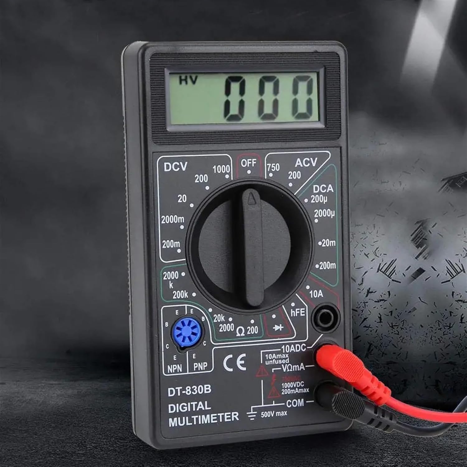
Figure 4.1: The DT830B Multimeter with the red test lead connected to the VΩmA jack and the black test lead connected to the COM jack, ready for most measurements.
5. Operating Instructions
Before taking any measurement, ensure the test leads are correctly connected and the rotary switch is set to the desired function and range.
5.1. Measuring DC Voltage (DCV)
- Connect the red lead to the "VΩmA" jack and the black lead to the "COM" jack.
- Set the rotary switch to the desired DCV range (e.g., 20V, 200V, 1000V). If the voltage is unknown, start with the highest range (1000V) and decrease as needed.
- Connect the test probes across the component or circuit to be measured, observing polarity.
- Read the voltage value on the LCD. If a negative sign appears, it indicates reversed polarity.
Ranges: 200mV, 2000mV, 20V, 200V, 1000V
5.2. Measuring AC Voltage (ACV)
- Connect the red lead to the "VΩmA" jack and the black lead to the "COM" jack.
- Set the rotary switch to the desired ACV range (e.g., 200V, 750V). Start with the highest range (750V) if the voltage is unknown.
- Connect the test probes across the AC voltage source.
- Read the voltage value on the LCD.
Ranges: 200V, 750V
5.3. Measuring DC Current (DCA)
Caution: Current measurements require the meter to be connected in series with the circuit. Ensure the circuit is de-energized before connecting the meter.
- For currents up to 200mA: Connect the red lead to the "VΩmA" jack and the black lead to the "COM" jack.
- For currents up to 10A: Connect the red lead to the "10ADC" jack and the black lead to the "COM" jack. (Note: The 10A range is unfused.)
- Set the rotary switch to the desired DCA range (e.g., 200µA, 20mA, 200mA, 10A). Start with the highest range if the current is unknown.
- Open the circuit where current is to be measured and connect the meter in series.
- Apply power to the circuit and read the current value on the LCD.
Ranges: 200µA, 2000µA, 20mA, 200mA, 10A
5.4. Measuring Resistance (Ω)
Caution: Ensure the circuit or component under test is completely de-energized before measuring resistance. Do not measure resistance on live circuits.
- Connect the red lead to the "VΩmA" jack and the black lead to the "COM" jack.
- Set the rotary switch to the desired Resistance range (e.g., 200Ω, 2kΩ, 20kΩ, 200kΩ, 2000kΩ). Start with a higher range if the resistance is unknown.
- Connect the test probes across the component to be measured.
- Read the resistance value on the LCD.
- For accurate readings, short the test leads together and note the reading. Subtract this value from subsequent measurements (Test Leads Shorted Clear).
Ranges: 200Ω, 2000Ω, 20kΩ, 200kΩ, 2000kΩ
5.5. Diode Test
- Connect the red lead to the "VΩmA" jack and the black lead to the "COM" jack.
- Set the rotary switch to the Diode symbol (→|→).
- Connect the red probe to the anode and the black probe to the cathode of the diode. The LCD will display the forward voltage drop (typically 0.5V to 0.8V for silicon diodes).
- Reverse the probes. The LCD should display "1" (open circuit) for a good diode. If it displays a value in both directions or "0", the diode is likely faulty.
5.6. Transistor hFE Test
- Set the rotary switch to the "hFE" position.
- Identify if the transistor is NPN or PNP.
- Insert the transistor's Emitter (E), Base (B), and Collector (C) leads into the corresponding holes in the hFE socket, ensuring correct NPN or PNP orientation.
- Read the hFE (DC current gain) value on the LCD.
5.7. "HV" Indicator
The "HV" indicator on the LCD display signifies a high voltage condition. Exercise extreme caution when this indicator is present.
5.8. Screen Values Jumping Explanation
It is normal for the displayed values to fluctuate or "jump" slightly, especially on sensitive ranges (small gear voltage/current sensitivity) or when the test leads are open. This can be due to the influence of external electrical atmospheres, including on-site electromagnetic fields or air static interference. This does not indicate a fault with the meter.
6. Maintenance
6.1. Battery Replacement
Refer to Section 4.1 for detailed instructions on replacing the 9V battery. Always replace the battery when the low battery indicator is displayed to ensure accurate measurements.
6.2. Cleaning
To clean the meter, wipe the case with a damp cloth and a mild detergent. Do not use abrasives or solvents. Ensure the meter is completely dry before use.
6.3. Fuse Replacement
The DT830B model does not feature user-replaceable fuses for the mA ranges. The 10A range is unfused. If the meter malfunctions, consult a qualified technician.
7. Troubleshooting
- Meter does not power on:
- Check if the 9V battery is installed correctly and has sufficient charge. Replace if necessary.
- Ensure the rotary switch is not in the "OFF" position.
- "1" or "OL" displayed on LCD:
- This indicates an over-range condition or an open circuit. Select a higher range or check the connection.
- For resistance measurements, it may indicate an open circuit or a resistance value higher than the selected range.
- Inaccurate readings:
- Check battery voltage; replace if low.
- Ensure test leads are fully inserted into the correct jacks.
- Verify the rotary switch is set to the correct function and range.
- Ensure the circuit under test is de-energized for resistance measurements.
- Be aware of external electromagnetic interference, which can cause minor fluctuations.
- No buzzer sound:
- Note that this specific model (DT830B) does not include a buzzer function. This is not a malfunction.
8. Specifications
| Function | Range | Accuracy |
|---|---|---|
| DC Voltage (DCV) | 200mV | ±(0.5% + 2 digits) |
| 2000mV | ±(0.5% + 2 digits) | |
| 20V | ±(0.5% + 2 digits) | |
| 200V | ±(0.5% + 2 digits) | |
| 1000V | ±(0.8% + 2 digits) | |
| AC Voltage (ACV) | 200V | ±(1.2% + 10 digits) |
| 750V | ±(1.2% + 10 digits) | |
| DC Current (DCA) | 2000µA | ±(1% + 2 digits) |
| 20mA | ±(1% + 2 digits) | |
| 200mA | ±(1.2% + 2 digits) | |
| 10A | ±(2% + 2 digits) | |
| Resistance (Ω) | 200Ω | ±(0.8% + 2 digits) |
| 2000Ω | ±(0.8% + 2 digits) | |
| 20kΩ | ±(0.8% + 2 digits) | |
| 200kΩ | ±(0.8% + 2 digits) | |
| 2000kΩ | ±(1% + 2 digits) | |
| Diode Test | Forward voltage drop display | |
| Transistor hFE Test | hFE value display | |
| Power Supply | 9V Battery (NEDA 1604 or 6F22 type) | |
| Display | 1999 counts, 0.5" high LCD | |
| Dimensions | Approx. 123 x 67 x 20mm (4.84 x 2.63 x 0.78 inches) | |
| Weight | Approx. 80g (excluding battery) | |
| Material | Polypropylene + Digital Accessories | |
9. Warranty and Support
Specific warranty information for the ESSISH DT830B Digital Multimeter is typically provided at the point of purchase or within separate documentation. Please refer to your purchase receipt or contact the retailer/manufacturer for details regarding warranty coverage and technical support.
For further assistance or inquiries, please contact ESSISH customer support through their official channels.