
Introduction
This manual provides essential information for the proper setup, operation, and maintenance of your RadioMaster ER5C-V2 ExpressLRS PWM Receiver. Please read this manual thoroughly before using the product to ensure safe and optimal performance.
The ER5C V2 receiver is built upon the high-performance ExpressLRS system, offering high reliability, flexible configuration, rapid response speeds, and an extended receiving range. It is designed for various surface and marine R/C applications.
Safety Information
Important: This product is not intended for use by children. Always operate remote-controlled devices responsibly and in accordance with local regulations.
- Ensure proper power supply voltage (DC 4.5-8.4V) to prevent damage.
- Avoid exposing the receiver to moisture or extreme temperatures.
- Always perform range checks before operating your model.
- Disconnect power when not in use or during maintenance.
Package Contents
Upon opening the package, verify that all components are present:
- 1 x ER5C V2 2.4GHz ELRS PWM Receiver
- 1 x Voltage Telemetry Wire
- 1 x User Card (Quick Start Guide)
Product Overview

Figure 1: Front view of the ER5C-V2 receiver. This image highlights the main body of the receiver, displaying the ExpressLRS 2.4 branding, the central boot button, and the clearly labeled PWM output channels (CH1-CH5) along with the battery input (BATT).

Figure 2: Angled view of the ER5C-V2 receiver. This perspective provides a better look at the PWM pin headers located at the bottom of the receiver, where servos and other components connect.

Figure 3: Side view of the ER5C-V2 receiver. This image illustrates the compact form factor of the device, highlighting its suitability for installations where space is limited.

Figure 4: Top-down angled view of the ER5C-V2 receiver. This view provides a clear perspective of the PWM pin headers from above, showing the arrangement for connecting various components.
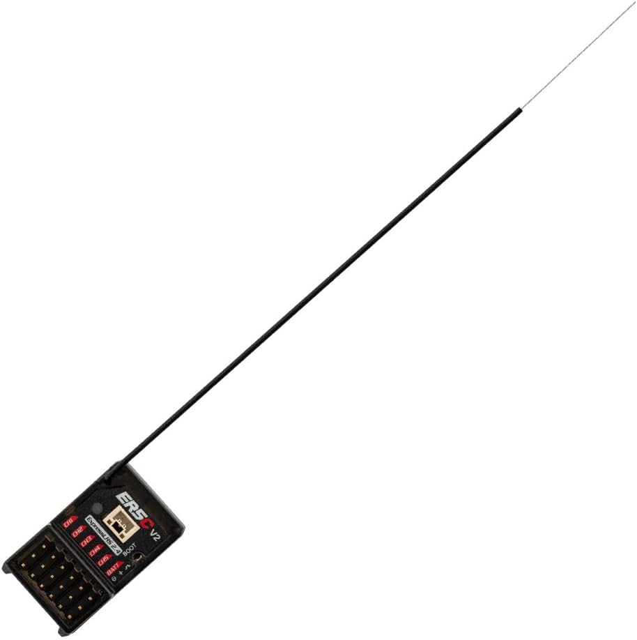
Figure 5: ER5C-V2 receiver with extended antenna. This image demonstrates the full length of the high-sensitivity antenna, crucial for optimal signal reception and range.

Figure 6: ER5C-V2 receiver with voltage telemetry wire. This image shows the receiver next to the dedicated wire used for external battery voltage telemetry, allowing monitoring of battery levels.
Setup
Binding Procedure
- Ensure your ExpressLRS transmitter module is updated to ELRS 3.3.0 or later.
- Power on the ER5C-V2 receiver. The LED on the receiver will flash slowly, indicating it is in binding mode.
- On your ExpressLRS transmitter, navigate to the ELRS LUA script and select "Bind".
- The receiver's LED should turn solid, indicating a successful bind. If not, repeat the process.
- After binding, power cycle both the transmitter and receiver to confirm the connection.
Wiring and Connections
The ER5C-V2 receiver features 5 PWM output channels and a dedicated battery input. Refer to the labels on the receiver for correct connections.
- CH1-CH5: Connect your servos, ESCs, or other PWM-controlled devices to these channels. Ensure correct polarity (Signal, Positive, Negative).
- BATT: This input is for the main power supply to the receiver (DC 4.5-8.4V). It also supports automatic detection of receiver battery/ESC BEC voltage for telemetry.
- Telemetry Wire: Use the included voltage telemetry wire to monitor external battery voltage (DC 4.0 - 35V). Connect the positive lead to the positive terminal of the battery you wish to monitor, and the negative lead to the negative terminal.
Operating Instructions
Powering On
Connect the receiver to a power source within the specified voltage range (DC 4.5-8.4V). The receiver will power on and attempt to establish a connection with the bound transmitter.
Telemetry Functionality
The ER5C-V2 supports voltage telemetry, automatically detecting either the receiver's power supply voltage or an external battery voltage via the dedicated telemetry wire. This data can be viewed on your compatible ExpressLRS transmitter.
Firmware Updates
The receiver supports Wi-Fi updates and WEBUI configuration. To update firmware:
- Power on the receiver without the transmitter powered on. The receiver will enter Wi-Fi mode.
- Connect your computer or mobile device to the Wi-Fi network broadcast by the receiver (SSID typically "ExpressLRS RX").
- Open a web browser and navigate to http://10.0.0.1 to access the WEBUI.
- Follow the on-screen instructions to flash new firmware or configure settings.
Maintenance
- Keep the receiver clean and free from dust and debris.
- Regularly inspect all wiring and connections for signs of wear or damage.
- Ensure the antenna is not kinked or damaged, as this can affect range and signal quality.
- Store the receiver in a dry, cool environment when not in use.
Troubleshooting
| Problem | Possible Cause | Solution |
|---|---|---|
| Receiver LED flashing slowly | Not bound to a transmitter or in binding mode. | Perform the binding procedure as described in the "Setup" section. |
| No control response | Receiver not bound, incorrect wiring, or power issue. | Verify binding, check all wiring connections (polarity), and ensure adequate power supply to the receiver and servos. |
| Poor range or signal loss | Damaged antenna, interference, or improper antenna placement. | Inspect antenna for damage. Ensure antenna is positioned away from carbon fiber or metal. Avoid operating near strong interference sources. |
| Telemetry data incorrect or missing | Telemetry wire not connected correctly or external battery voltage out of range. | Check the connection of the voltage telemetry wire. Ensure the monitored voltage is within DC 4.0 - 35V. |
Specifications
| Feature | Detail |
|---|---|
| Item | ER5C V2 2.4GHz ELRS PWM Receiver |
| Power Supply | DC 4.5-8.4V |
| Antenna Type | High-sensitivity antenna |
| Wireless Protocol | ELRS 3.3.0 (pre-installed) |
| Channels | 5 PWM Channels |
| Telemetry Voltage Detection Range | DC 4.0 - 35V |
| RF Telemetry | Yes |
| Telemetry Power | 10mW |
| Weight | 5.7 grams |
| Dimensions (L x W x H) | 30.0 x 18.5 x 13.0mm |
| Built-in | TCXO (Temperature Compensated Crystal Oscillator) |
| Firmware Device Category | RadioMaster 2.4 GHz |
| Firmware Device | RadioMaster ER5C 2.4GHz PWM RX |
| Country of Origin | China |
| Manufacturer's Recommended Age | 12 months - 4 years (Note: This age range is typically for toys and may not reflect the technical nature of this product.) |
Warranty and Support
For warranty information and technical support, please contact your retailer or the manufacturer, RadioMaster - Helidirect. Keep your proof of purchase for any warranty claims.
Manufacturer: RadioMaster - Helidirect