1. Introduction
This manual provides essential information for the proper installation, operation, and maintenance of the Fabater DC Motor Driver Module. Please read this manual thoroughly before using the product to ensure safe and efficient operation.
2. Product Overview
The Fabater DC Motor Driver Module is an H-bridge design capable of driving two high-power DC motors. It features high integration and efficient heat dissipation, making it suitable for various applications requiring precise motor control.
2.1 Key Features
- High Integration: The module incorporates SMD components for a compact and well-laid-out design, featuring two high-power DC motor drivers on board.
- Efficient Heat Dissipation: Equipped with a wide heat sink to effectively dissipate heat, ensuring stability during high current operation.
- High Switching Frequency: Operates at up to 60KHz, which helps in avoiding low-frequency motor debugging issues.
- High Current Capability: Supports a maximum rated current of up to 60A per motor, with a low on-resistance of only 0.003 ohm.
- Wide Compatibility: Compatible with 3.3V and 5V microcontrollers, requiring only a single motor power supply (12V-30V).
2.2 Product Visuals

Figure 1: Top view of the Fabater DC Motor Driver Module. This image shows the green heat sink covering the main driver chips, flanked by two large capacitors, and blue screw terminal blocks for power and motor connections.

Figure 2: Top and bottom views of the module. The top view displays the heat sink and terminals, while the bottom view shows the PCB traces, motor connection points (M), and power input labels (N:+9V-30V, N:GND(-)).

Figure 3: Angled perspective of the motor driver module, highlighting the compact design and component layout.
3. Specifications
| Parameter | Value |
|---|---|
| Model Number | Fabatereufwvptdxg |
| Brand | Fabater |
| Wide Voltage Input | 9V - 30V DC |
| Rated Current (per channel) | 60A |
| On-Resistance | 0.003 ohm |
| Switching Frequency | Up to 60KHz |
| Control Voltage Compatibility | 3.3V and 5V microcontrollers |
| Material | Copper (PCB) |
| Item Weight | 1.41 ounces |
| Package Dimensions | 4.72 x 3.15 x 0.79 inches |
4. Setup
Careful attention to wiring is crucial for the correct and safe operation of the motor driver module. Refer to the diagrams below for connection details.
4.1 Connection Diagram
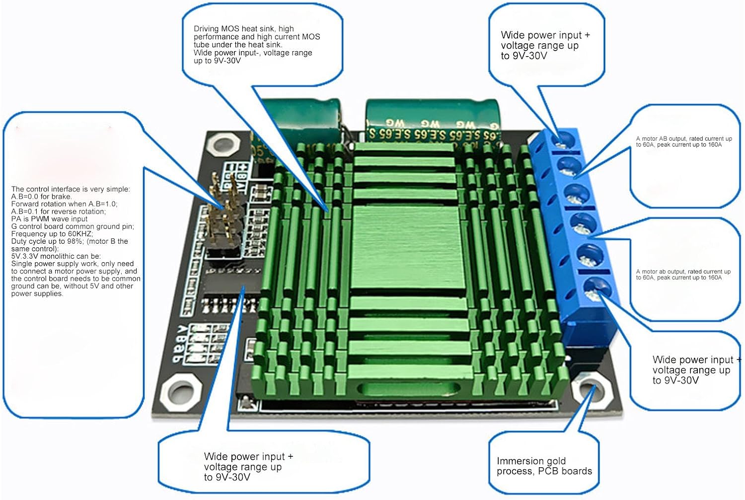
Figure 4: Detailed connection diagram. This image illustrates the wide voltage input (9V-30V), motor AB output (rated 60A, peak 160A), motor ab output (rated 60A, peak 160A), and the control interface pins. It also highlights the driving MOS heat sink and immersion gold process PCB.

Figure 5: Pinout diagram for the control interface. This diagram specifies the GND (-) power input negative, Motor AB output, Motor ab output, V+ power input positive (9V-30V), 5V (+) output, Direction B, Direction A, 15K square wave, Direction b, Direction a, and Motor AB turn indicators.
4.2 Power Connections
- Connect your DC power supply to the blue screw terminal block labeled V+ (positive) and GND(-) (negative). The module supports a wide input voltage range of 9V to 30V.
- Connect your DC motors to the other blue screw terminal blocks. There are two sets of outputs: Motor AB and Motor ab. Each set can drive one DC motor.
4.3 Control Interface Connections
The control interface uses a standard pin header. Connect your microcontroller (3.3V or 5V compatible) to these pins:
- GND (-): Connect to the ground of your microcontroller.
- 5V (+): This is an output pin, providing 5V. Do not use as an input power source.
- Direction A / Direction B: Control pins for Motor AB.
- Direction a / Direction b: Control pins for Motor ab.
- PWM: Pulse Width Modulation input for speed control. The duty cycle range is 0% to 98%.
- 15K Square Wave: This refers to the internal switching frequency.
5. Operating Instructions
The module allows for independent control of two DC motors. The control logic for each motor channel (AB and ab) is identical.
5.1 Motor Direction Control
To control the direction of a motor, use the corresponding Direction pins (e.g., Direction A and Direction B for Motor AB). The logic is as follows:
- Brake: Set both Direction A and Direction B to LOW (0).
- Forward Rotation: Set Direction A to HIGH (1) and Direction B to LOW (0).
- Reverse Rotation: Set Direction A to LOW (0) and Direction B to HIGH (1).
Note: The specific 'forward' or 'reverse' direction depends on how your motor is wired to the A/B terminals. If the direction is opposite to what is desired, simply swap the motor wires.
5.2 Motor Speed Control (PWM)
Motor speed is controlled by applying a Pulse Width Modulation (PWM) signal to the PWM input pin. The module supports a PWM duty cycle from 0% to 98%.
- A 0% duty cycle will stop the motor.
- Increasing the duty cycle (e.g., from 1% to 98%) will increase the motor speed.
- The maximum effective duty cycle is 98%.
5.3 Operational Video
Video 1: Overview of the DC Motor Driver Module. This video provides a general visual presentation of the product, showing its physical appearance and components.
6. Maintenance
The Fabater DC Motor Driver Module is designed for reliable operation with minimal maintenance. Follow these guidelines:
- Keep Clean: Ensure the module is free from dust, dirt, and moisture. Use a soft, dry brush or compressed air for cleaning.
- Inspect Connections: Periodically check all wiring connections to ensure they are secure and free from corrosion. Loose connections can lead to intermittent operation or damage.
- Thermal Management: Ensure adequate airflow around the module, especially the heat sink, to prevent overheating during prolonged high-current operation. Do not obstruct the heat sink.
- Avoid Overload: Do not exceed the specified maximum current (60A per channel) to prevent damage to the module.
7. Troubleshooting
If you encounter issues with your Fabater DC Motor Driver Module, consider the following troubleshooting steps:
- Motor Not Responding:
- Verify power supply connections (9V-30V DC) and ensure the power supply is active.
- Check motor connections for proper polarity and secure contact.
- Confirm control signal connections from the microcontroller are correct and active (Direction pins, PWM).
- Ensure the control logic for direction (e.g., A=1, B=0) is correctly applied.
- Motor Runs in Wrong Direction:
- Swap the motor wires connected to the A/B (or a/b) terminals.
- Review your microcontroller code for correct direction logic.
- Motor Speed Issues:
- Verify the PWM signal is being generated correctly by your microcontroller.
- Check the duty cycle range (0-98%).
- Ensure the motor is not overloaded, which can prevent it from reaching desired speeds.
- Module Overheating:
- Ensure adequate ventilation around the module.
- Reduce the load on the motors if they are drawing excessive current.
- Verify that the motor current does not consistently exceed the rated 60A.
If problems persist after following these steps, contact customer support for further assistance.
8. Warranty and Support
Specific warranty information for the Fabater DC Motor Driver Module is not provided in this manual. Please refer to the product packaging or the retailer's website for details regarding warranty coverage and return policies.
For technical support or inquiries, please contact your point of purchase or the manufacturer directly.