Pissente AT5-1500X
Pissente AT5-1500X Variable Frequency Drive User Manual
Model: AT5-1500X | Brand: Pissente
1. Introduction
This manual provides essential information for the safe and efficient operation of your Pissente AT5-1500X Variable Frequency Drive (VFD). The AT5-1500X is designed to control the speed of 3-phase motors, offering high torsion and a wide speed regulation range. It features a single-phase 110VAC input and a 3-phase 220VAC output, with a power rating of 1500W. Please read this manual thoroughly before installation, operation, or maintenance to ensure proper use and prevent potential hazards.
2. Safety Precautions
Failure to follow these safety instructions may result in death, severe injury, or property damage. Always prioritize safety during installation, operation, and maintenance.
- Power Disconnection: Always ensure the power supply is completely disconnected before performing any wiring, inspection, or maintenance on the inverter.
- Correct Wiring: It is strictly forbidden to connect the U, V, W output terminals to the AC power supply. Incorrect wiring will cause severe damage to the inverter.
- Grounding: The ground terminal of the inverter must be properly and securely grounded to prevent electrical shock.
- Installation Environment: Do not install the inverter in environments with flammable or explosive gases, as this poses a significant risk of explosion. Ensure adequate ventilation.
- Professional Installation: Wiring and internal adjustments should only be performed by qualified professionals. The inverter contains high-voltage components; do not open the casing casually.
- Protection Features: The device includes comprehensive protection against overcurrent, overvoltage, undervoltage, module failure, overheating, and short circuits. However, these features do not negate the need for careful handling and adherence to safety protocols.

Image: Front view of the AT5-1500X VFD, showing the safety precaution label on the lower front panel. This label outlines critical warnings regarding power, wiring, grounding, and installation environment.
3. Product Features
The Pissente AT5-1500X VFD is equipped with advanced features for reliable motor control:
- Comprehensive Protection: Features built-in safeguards against overcurrent, overvoltage, undervoltage, module failure, overheating, and short circuits. It also provides low electromagnetic interference.
- Clear Digital Display: An integrated digital display offers clear readings and facilitates convenient parameter settings for easy monitoring and customization of speed.
- High-Performance Speed Adjustment: Provides precise speed adjustment for motors with high torsion and a wide regulation range, ensuring optimal motor performance.
- Durable Construction: Constructed from robust plastic material, ensuring impact resistance and long-term durability for enhanced safety and reliability.
- Versatile Application: Suitable for various applications including 3-phase motor speed regulation, lighting adjustment, and power cooling.
4. Package Contents
Upon unpacking, please verify that all items are present and undamaged:
- 1 x Pissente AT5-1500X Inverter
- 1 x User Manual (this document)
5. Specifications
| Parameter | Value |
|---|---|
| Model | AT5-1500X |
| Power | 1500W |
| Power Phase Number | Single phase input, Three phase output |
| Input Voltage | 110VAC 50/60Hz |
| Output Voltage | 220VAC |
| Material | Plastic |
| Display Type | Digital |
| Item Weight | 2.86 pounds (approx. 1.3 kg) |
| Package Dimensions | 8.66 x 7.87 x 6.69 inches (approx. 22 x 20 x 17 cm) |
6. Setup and Installation
Proper installation is crucial for the safe and effective operation of the VFD. It is highly recommended that installation be performed by a qualified electrician.
6.1 Mounting
- Mount the VFD vertically on a stable, non-flammable surface.
- Ensure sufficient clearance around the unit for proper ventilation and heat dissipation. Avoid enclosed spaces.
- Keep the VFD away from direct sunlight, excessive dust, corrosive gases, and moisture.

Image: Angled view of the AT5-1500X VFD, highlighting the ventilation grilles on the sides and cooling fans at the bottom, essential for heat dissipation during operation.
6.2 Wiring
WARNING: Ensure all power is disconnected before wiring. Incorrect wiring can cause severe damage to the unit and pose electrical hazards.
- Input Power (Single Phase 110VAC): Connect the single-phase 110VAC power supply to the designated input terminals (typically marked L and N or R and S).
- Output Power (Three Phase 220VAC): Connect the 3-phase motor to the output terminals (typically marked U, V, W). Do not connect these terminals to the main AC power supply.
- Grounding: Connect the ground terminal (marked with the ground symbol) to a reliable earth ground. This is critical for safety.
- Control Wiring (Optional): If external control signals (e.g., start/stop, speed reference) are used, refer to the detailed wiring diagram in the full technical manual (if provided separately) for correct connections.

Image: Top-down view of the AT5-1500X VFD, showing the internal heatsink and the area where power and motor terminals are located. Proper wiring to these terminals is essential.
7. Operating Instructions
The AT5-1500X features a user-friendly control panel for easy operation and parameter adjustment.
7.1 Control Panel Overview
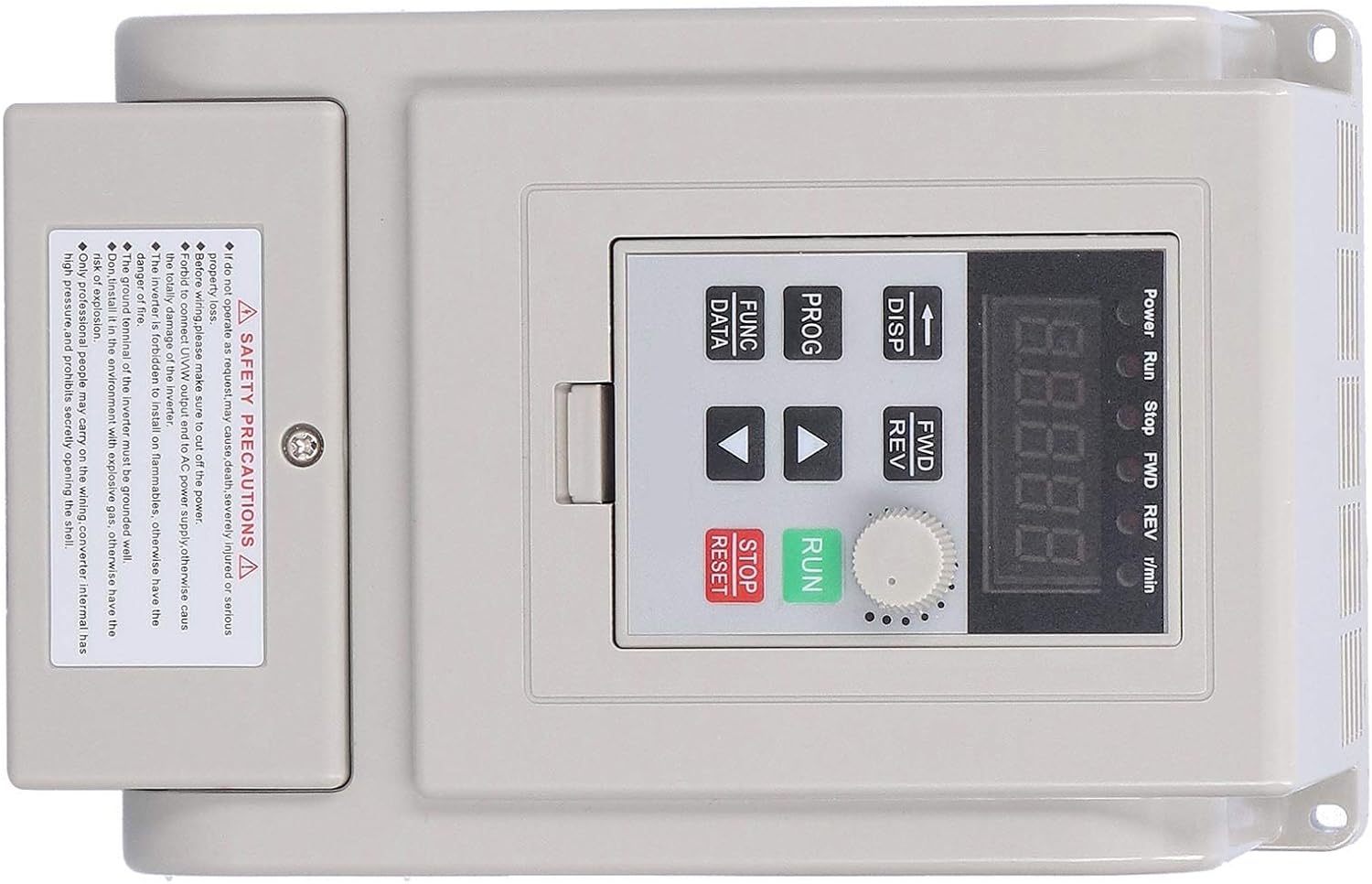
Image: Close-up view of the AT5-1500X VFD control panel, showing the digital display, rotary knob, and various function buttons for operation and parameter settings.
- Digital Display: Shows current operating status, frequency, and parameter values.
- Power/Run/Stop/FWD/REV Indicators: LEDs indicating the VFD's status.
- DISP Button: Toggles display modes (e.g., output frequency, output current).
- PROG Button: Enters/exits parameter programming mode.
- FUNC/DATA Button: Used to select parameters or confirm data entry.
- Up/Down Arrows: Navigate through parameters or adjust values.
- FWD/REV Button: Changes motor rotation direction (Forward/Reverse).
- Rotary Knob: Fine-tunes frequency or parameter values.
- RUN Button: Starts the motor.
- STOP/RESET Button: Stops the motor or resets fault alarms.
7.2 Basic Operation
- Power On: After ensuring correct wiring, apply power to the VFD. The digital display will light up.
- Set Frequency: Use the Up/Down arrow buttons or the rotary knob to set the desired output frequency. The display will show the current frequency.
- Start Motor: Press the RUN button to start the motor. The "Run" indicator will illuminate.
- Adjust Speed: While the motor is running, use the Up/Down arrows or rotary knob to adjust the motor speed.
- Change Direction: Press the FWD/REV button to switch the motor's rotation direction.
- Stop Motor: Press the STOP/RESET button to stop the motor. The "Stop" indicator will illuminate.
7.3 Parameter Settings
To access and modify advanced parameters (e.g., acceleration/deceleration time, motor parameters), follow these general steps:
- Press the PROG button to enter parameter programming mode. The display will show a parameter code (e.g., P001).
- Use the Up/Down arrows to navigate through the parameter codes.
- Press FUNC/DATA to view the current value of the selected parameter.
- Use the Up/Down arrows or rotary knob to adjust the parameter value.
- Press FUNC/DATA again to save the new value.
- Press PROG to exit programming mode.
Note: A detailed list of parameters and their functions can be found in the comprehensive technical manual. Incorrect parameter settings can lead to motor damage or improper operation.
8. Maintenance
Regular maintenance helps ensure the longevity and optimal performance of your VFD.
- Cleaning: Periodically clean the exterior of the VFD with a soft, dry cloth. Ensure ventilation grilles are free from dust and debris to prevent overheating. Do not use liquid cleaners.
- Ventilation: Verify that the cooling fans (if present) are operating correctly and that airflow is not obstructed.
- Connections: Regularly inspect all wiring connections for tightness and signs of corrosion or damage. Loose connections can lead to poor performance or safety hazards.
- Environmental Check: Ensure the operating environment remains within specified temperature and humidity ranges, and free from excessive dust or corrosive substances.

Image: Internal view of the AT5-1500X VFD, showing the heatsink fins. Keeping these clear of dust is vital for efficient cooling and preventing overheating.
9. Troubleshooting
If you encounter issues with your VFD, refer to the following common troubleshooting steps. For complex problems, contact technical support.
| Problem | Possible Cause | Solution |
|---|---|---|
| VFD does not power on | No input power; loose connections; internal fault. | Check power supply and connections. Ensure circuit breaker is on. If problem persists, contact support. |
| Motor does not start | Incorrect wiring; parameter settings; fault condition. | Verify motor and power wiring. Check for fault codes on display. Ensure RUN command is issued. Review parameter settings. |
| Motor runs erratically or at wrong speed | Incorrect frequency setting; motor parameters mismatch; interference. | Adjust frequency. Verify motor parameters (voltage, current, frequency) are correctly set in the VFD. Check for sources of electromagnetic interference. |
| Overcurrent/Overload fault | Motor overload; short circuit in motor/cables; acceleration time too short. | Reduce motor load. Check motor and cables for damage. Increase acceleration time parameter. |
| Overvoltage/Undervoltage fault | Unstable input power; regeneration during deceleration; incorrect voltage setting. | Check input power supply stability. Increase deceleration time. Verify input voltage matches VFD specification. |
| Overheat fault | Insufficient ventilation; high ambient temperature; clogged heatsink. | Ensure proper ventilation and clear any obstructions. Reduce ambient temperature if possible. Clean heatsink fins. |
If a fault occurs, the VFD's digital display will typically show an error code. Refer to the full technical manual for a complete list of error codes and their specific remedies. After resolving a fault, press the STOP/RESET button to clear the alarm.
10. Warranty and Support
For warranty information, technical support, or service inquiries, please contact your original point of purchase or the manufacturer, Pissente. Ensure you have your product model number (AT5-1500X) and purchase details available when contacting support.
Manufacturer: Pissente
Model: AT5-1500X