
1. Introduction
The ESSISH ETC-961 is a versatile digital temperature controller designed for precise temperature management in various applications, including defrosting refrigerators and heating systems. It features a clear digital display and utilizes an NTC sensor for accurate temperature measurement. This manual provides essential information for the safe and effective installation, operation, and maintenance of your ETC-961 controller.
2. Safety Information
Please read all safety instructions carefully before installation and operation to prevent damage to the device or personal injury.
- Power Supply Verification: Confirm that the power voltage supplied to the controller meets the specified requirements (230VAC±10% 50/60Hz). Incorrect voltage can lead to improper operation or permanent damage to the instrument.
- Wiring Precautions: Ensure that probe down-leads and power wires are kept at a proper distance from each other to avoid potential electromagnetic interference, which could affect the controller's accuracy and performance.
- Qualified Personnel: Installation and wiring should only be performed by qualified personnel familiar with electrical systems and safety standards.
- Environmental Conditions: Do not expose the controller to excessive moisture, dust, or corrosive environments.
- Disconnection: Always disconnect power before performing any wiring, maintenance, or inspection.
3. Product Overview
The ETC-961 features a compact design with a clear digital display and intuitive controls for easy operation.

Figure 3.1: Front view of the ETC-961 Digital Temperature Controller.
3.1 Front Panel and Buttons

Figure 3.2: ETC-961 Front Panel with labeled controls.
- Digital Display: Shows the current temperature and various parameter settings.
- UP Arrow Button (▲): Used to increase values or navigate menu options.
- DOWN Arrow Button (▼): Used to decrease values or navigate menu options.
- SET Button: Used to enter parameter setting mode, confirm selections, or view current setpoint.
- FNC Button (Function): Used to access advanced functions or switch between modes.
- Indicators: Icons for fan operation, defrosting, and heating/cooling status are present on the display.
4. Installation and Setup
4.1 Mounting
The ETC-961 is designed for panel mounting. Ensure adequate space for ventilation and wiring connections.

Figure 4.1: ETC-961 Product Dimensions. Mounting size: Length 71mm × Width 29mm.
4.2 Wiring Diagram
Refer to the following diagrams for correct wiring connections. Ensure all connections are secure and comply with local electrical codes.

Figure 4.2: ETC-961 Wiring Diagram (Top View).
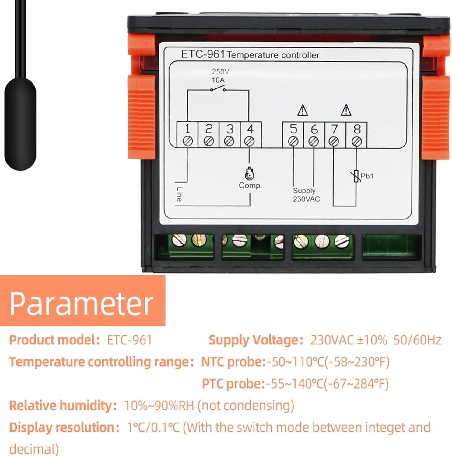
Figure 4.3: ETC-961 Detailed Wiring Diagram.
Terminal Connections:
- Terminals 1 & 2: Line (Power Input)
- Terminals 3 & 4: Compressor (Comp.) Output (Rated current: 10A/220VAC)
- Terminals 5 & 6: Power Supply 230VAC
- Terminals 7 & 8: NTC Sensor (Pb1) Input
Important: The NTC sensor probe wire length is 2 meters. Ensure the sensor is placed in the desired temperature monitoring location, away from direct heat sources or drafts that could affect readings.
5. Operating Instructions
5.1 Power On
Once correctly wired and powered, the controller's digital display will illuminate, showing the current temperature measured by the NTC sensor.
5.2 Setting the Temperature Setpoint
- Press and hold the SET button for approximately 3 seconds until the display flashes.
- Use the UP (▲) or DOWN (▼) arrow buttons to adjust the desired temperature setpoint.
- Press the SET button again to confirm the new setpoint and exit the setting mode.
5.3 Accessing Function Parameters
The ETC-961 has various configurable parameters for defrosting, differential, and other control settings. Specific parameter codes and their functions are typically detailed in a separate parameter list (not provided in this general manual). To access these:
- Press and hold the FNC button for several seconds to enter the function parameter menu.
- Use the UP (▲) or DOWN (▼) arrow buttons to scroll through the parameter codes.
- Press SET to view the value of a selected parameter.
- Use UP (▲) or DOWN (▼) to modify the value.
- Press SET to save the new value.
- Press FNC again to exit the function parameter menu.
6. Maintenance
- Cleaning: Regularly wipe the controller's surface with a soft, dry cloth. Do not use abrasive cleaners or solvents.
- Sensor Inspection: Periodically check the NTC sensor and its wiring for any signs of damage or corrosion. Ensure the sensor is clean and free from obstructions that could impede accurate temperature readings.
- Connection Check: Ensure all electrical connections remain tight and secure. Loose connections can lead to intermittent operation or electrical hazards.
7. Troubleshooting
This section addresses common issues you might encounter with the ETC-961 controller.
| Problem | Possible Cause | Solution |
|---|---|---|
| Controller does not power on / No display | No power supply; Incorrect wiring; Blown fuse (external) | Check power source; Verify wiring connections according to diagram; Inspect external fuse if applicable. |
| Incorrect temperature reading | Faulty NTC sensor; Sensor not properly connected; Sensor placed in an unsuitable location | Check sensor connection (Terminals 7 & 8); Replace sensor if damaged; Relocate sensor to a representative area. |
| Controller not responding to button presses | Temporary software glitch; Buttons stuck | Power cycle the device (turn off and on); Ensure buttons are not physically obstructed. |
| Output (e.g., compressor) not activating | Setpoint not reached; Differential setting too wide; Output wiring issue; Faulty relay | Verify setpoint and current temperature; Check differential parameter; Inspect output wiring (Terminals 3 & 4); Consult a technician if relay is suspected. |
8. Specifications
| Parameter | Value |
|---|---|
| Power Supply | 230VAC ±10% 50/60Hz |
| Rated Current of Relays (Refrigeration) | 10A/220VAC |
| Operating Temperature | -5°C to 55°C |
| Relative Humidity | 10%-90%RH (non-condensing) |
| Storage Temperature | -30°C to 85°C |
| Temperature Controlling Range (NTC Probe) | -50°C to 110°C (-58°F to 230°F) |
| Temperature Controlling Range (PTC Probe) | -55°C to 140°C (-67°F to 284°F) |
| Display Resolution | 1°C / 0.1°C (switchable) |
| Accuracy (NTC) | ±0.5°C (-30°C to 50°C), otherwise ±1°C |
| Accuracy (PTC) | ±1°C (-30°C to 50°C), otherwise ±2°C |
| Probe Type | NTC (-50°C to 120°C); PTC (-50°C to 150°C) |
| Product Dimensions (L x W x D) | 77mm x 34.5mm x 58mm |
| Mounting Size (L x W) | 71mm x 29mm |
| Probe Wire Length | 2 meters (including the probe) |
| Item Weight | 50 Grams (1.76 ounces) |
9. Warranty and Support
For warranty information and technical support, please refer to the documentation provided with your purchase or contact your retailer. Keep your purchase receipt as proof of purchase.