1. Introduction
This manual provides detailed instructions for the MMUNNA EK-3010 Digital Temperature Controller. This device is designed for precise temperature control in mid to low-temperature cold storage or heating applications. It offers temperature measurement, display, and control functionalities, along with features such as temperature calibration, over-temperature alarms, and sensor failure detection. The controller also includes a one-key recovery function for default parameters and a key lock feature for enhanced security.
The EK-3010 model specifically supports refrigeration and heating functions with a single NTC sensor input.
2. Product Overview and Features
2.1 Key Features
- Six touch key design for quick parameter setting and easy operation.
- One-key recovery function for preset parameters.
- Temperature calibration capability.
- Over-temperature alarm function.
- Sensor failure alarm function.
- Key lock function to prevent accidental changes.
2.2 Functionality
- Single NTC sensor input for cabinet temperature measurement.
- One-way control output for refrigeration or heating equipment.
- Integrated buzzer alarm output.

Image Description: A front-angled view of the MMUNNA Digital Temperature Controller. The device is gray and black with a red digital display showing '29.4'. It features touch buttons labeled 'On Temp', 'Off Temp', 'Up Arrow', 'Down Arrow', and 'OK/Lock'. The model number 'EK-3020' is visible on the front, indicating a similar interface to the EK-3010.
3. Technical Specifications
| Parameter | Value |
|---|---|
| Measuring Range | -40°C to 99°C |
| Controlling Range | -40°C to 85°C |
| Accuracy | -30°C to 50°C: ±0.5°C; Others: ±2°C |
| Resolution | 0.1°C / 1°C |
| Mounting Size | 71mm x 29mm |
| Power Supply | 220V ±10% (VAC), 50/60Hz |
| Power Consumption | <5W |
| Refrigeration Output | 10A/220VAC (or 16A/220VAC, directly drives single-phase compressor 1HP) |
| Work Ambient Temperature | -5°C to 60°C |
| Work Ambient Humidity | 10% to 90% non-condensing |
| Storage Temperature | -25°C to 75°C |
| Sensor Type | NTC (10kΩ/25°C, B value 3435K) |
| Sensor Length | 2 meters |

Image Description: A graphic illustrating the temperature control range of the MMUNNA Digital Temperature Controller. It shows a range from -40°C to 85°C for control and -40°C to 99°C for measurement, depicted with a circular gradient scale.
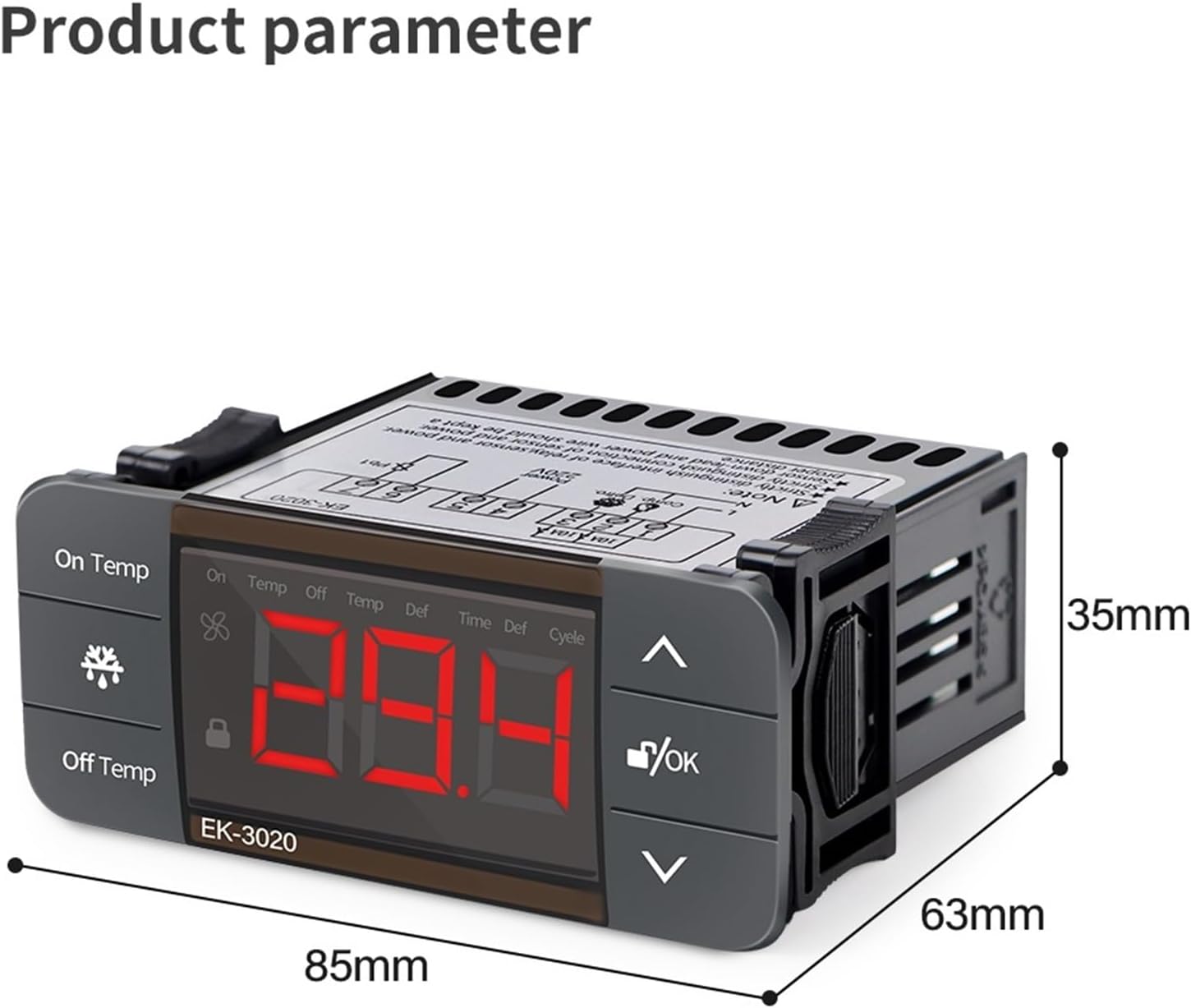
Image Description: A side view of the MMUNNA Digital Temperature Controller, showing its physical dimensions. The width is indicated as 85mm and the height as 35mm. The image helps in understanding the mounting requirements.
4. Installation and Wiring
Important Safety Note: Always ensure the power supply is disconnected before performing any installation or wiring to prevent electric shock. All electrical work should be carried out by a qualified professional.
The controller is designed for panel mounting. Ensure the mounting hole dimensions are 71mm x 29mm to properly secure the device.
4.1 Wiring Diagram for EK-3010

Image Description: This image displays the wiring diagram for the MMUNNA EK-3010 Digital Temperature Controller. It illustrates six terminals. Terminals 1 and 2 are designated for the compressor (Comp.) output, connected to the Live (L) and Neutral (N) lines. Terminals 3 and 4 are for the 220V power supply (L and N). Terminals 5 and 6 are for the NTC sensor (Pb1). A note indicates a 10A fuse for the compressor output.
- Terminals 1 & 2 (Output): Connect these terminals to your refrigeration or heating equipment (e.g., compressor). Ensure the connected load does not exceed the specified output capacity of 10A/220VAC (or 16A/220VAC for a 1HP compressor).
- Terminals 3 & 4 (Power Input): Connect these terminals to your 220V AC, 50/60Hz power supply.
- Terminals 5 & 6 (Sensor Input): Connect the NTC temperature sensor to these terminals.
5. Operation
5.1 Display Interface

Image Description: This image shows the front panel of the MMUNNA EK-3020 Digital Temperature Controller, which has a similar interface to the EK-3010. It features a large red LED display in the center. On the left, there are 'On Temp' and 'Off Temp' buttons. On the right, there are 'Up' and 'Down' arrow buttons, and an 'OK/Lock' button. A black NTC sensor with a 2-meter cable is shown below the controller.
The controller features a large LCD screen for clear data display and responsive touch keys for adjustments.
5.2 Key Functions
- Up Arrow Key: Used to increase numerical values or navigate upwards through menu options.
- Down Arrow Key: Used to decrease numerical values or navigate downwards through menu options.
- OK / Lock Key: Confirms selected settings or parameters. This key also functions to lock and unlock the keypad.
5.3 Setting Temperature and Parameters
To set the desired temperature and other operational parameters, refer to the detailed programming guide provided with your controller. The six touch keys allow for quick and intuitive parameter adjustments.
5.4 Key Lock Function
The controller includes a key lock function to prevent unintended changes to settings. To activate or deactivate this feature, press and hold the OK/Lock key for a few seconds. Refer to the full programming manual for specific instructions on using the key lock.
6. Maintenance
- Cleaning: Regularly clean the controller's surface with a soft, dry cloth. Avoid using abrasive cleaners, solvents, or excessive moisture, as these can damage the device.
- Sensor Inspection: Periodically inspect the NTC sensor cable for any signs of damage, kinks, or wear. A damaged sensor can lead to inaccurate temperature readings.
- Connection Check: Ensure all wiring connections remain secure and free from corrosion. Loose connections can affect performance and safety.
- Environmental Conditions: Do not expose the controller to environments with excessive moisture, dust, or temperatures outside its specified operating range (-5°C to 60°C).
7. Troubleshooting
7.1 Common Issues and Solutions
- Temperature Over-Temperature Alarm:
- Cause: The measured temperature has exceeded the configured high-temperature alarm limit.
- Solution: Verify the conditions of the controlled environment. Adjust the temperature set points or alarm limits if necessary. Ensure that the cooling or heating equipment is functioning correctly.
- Sensor Failure Alarm:
- Cause: The NTC temperature sensor is faulty, disconnected, or has a short circuit.
- Solution: Inspect the sensor cable for any physical damage. Confirm that the sensor is properly connected to terminals 5 and 6. If damage is found or connections are secure but the alarm persists, replace the sensor.
- Controller Not Powering On:
- Cause: No power supply or incorrect wiring to the power input.
- Solution: Check that the 220V AC power supply is active and correctly connected to terminals 3 and 4 of the controller.
- Keypad Unresponsive:
- Cause: The keypad lock function is currently active.
- Solution: Press and hold the OK/Lock key for a few seconds to unlock the keypad. Refer to the programming manual for specific unlock procedures if needed.
8. Warranty and Support
Specific warranty information is not provided in the product description. For any warranty claims, technical assistance, or support inquiries, please contact your retailer or the manufacturer, MMUNNA, directly. It is recommended to retain your purchase receipt as proof of purchase.


