
1. Introduction
The ESSISH ETC-974 is a versatile temperature controller designed for refrigeration, defrosting, and heating applications. It features dual NTC sensors for precise temperature measurement and control, making it suitable for various industrial and commercial settings, including cold storage and display cabinets. This manual provides detailed instructions for installation, operation, and maintenance to ensure optimal performance and longevity of your device.
2. Product Features
- Multi-functional temperature control for refrigeration, defrosting, and heating.
- Equipped with dual NTC sensors for accurate temperature monitoring.
- Wide temperature measurement range: -50°C to 110°C (NTC probe).
- High display resolution of 1°C/0.1°C (switchable).
- Multiple relay outputs for compressor, defrost, and fan control.
- Clear digital display for easy reading of temperature and settings.
- Compact design for easy integration into various systems.
3. Specifications
| Parameter | Value |
|---|---|
| Model | ETC-974 |
| Temperature Measure Range (NTC) | -50~110°C (-58~230°F) |
| Temperature Measure Range (PTC) | -55~140°C (-67~284°F) |
| Display Resolution | 1°C / 0.1°C (switchable) |
| Accuracy (NTC) | ±0.5°C (-30°C~50°C); other ±1°C |
| Accuracy (PTC) | ±1°C (-30°C~50°C); other ±2°C |
| Probe Type | NTC (-50°C~120°C); PTC (-50°C~150°C) |
| Power Supply | 230VAC ±10% ; 50/60Hz |
| Rated Current of Relays (Refrigeration, Defrost, Fan) | 8A / 220VAC |
| Operating Temperature | -5°C~55°C |
| Relative Humidity | 10%-90%RH (non-condensing) |
| Storage Temperature | -30°C~85°C |
| Sensor Input | 2 NTC sensors |
| Sensor Length | 2 meters (including probe) |
| Package Dimensions | 1.18 x 0.79 x 0.39 inches |
| Item Weight | 1.76 ounces (50 Grams) |
| Manufacturer | ESSISH |
| Country of Origin | China |
4. Safety Information
Please read and understand all safety instructions before installing or operating the ETC-974 temperature controller. Failure to follow these instructions may result in electric shock, fire, or serious injury.
- Ensure the power supply matches the controller's specifications (230VAC).
- Disconnect power before performing any wiring or maintenance.
- All wiring should be performed by a qualified electrician in accordance with local electrical codes.
- Do not operate the device in environments with excessive humidity or corrosive gases.
- Keep the device away from water and direct sunlight.
- Do not disassemble or modify the controller.
5. Product Overview and Components

Figure 5.1: Front view of the ETC-974 Temperature Controller, showing the digital display and control buttons.

Figure 5.2: Close-up of the ETC-974 front panel with control buttons (UP, DOWN, FNC, SET) clearly labeled.

Figure 5.3: ETC-974 controller showing its dimensions (width, height, depth) and the two NTC temperature sensors included.
6. Installation and Setup
6.1 Mounting
The ETC-974 is designed for panel mounting. Ensure there is adequate space for ventilation and wiring connections. Cut an opening in the panel according to the controller's dimensions (refer to Figure 5.3 for exact measurements). Secure the controller using the provided clips or mounting hardware.
6.2 Wiring Diagram
Carefully follow the wiring diagram below. Incorrect wiring can damage the device or cause safety hazards. Ensure all connections are secure and properly insulated.

Figure 6.1: Detailed wiring diagram for the ETC-974, showing connections for Line, Defrost, Compressor, Fan, Supply, and NTC sensors (Pb1, Pb2).
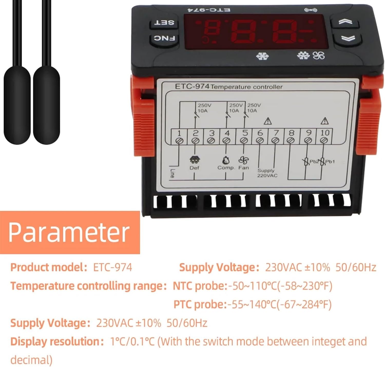
Figure 6.2: Top view of the ETC-974 showing the terminal block with corresponding wiring labels for power supply, relays, and sensors.
- Power Supply (220VAC): Connect the main power supply to terminals labeled 'Supply 220VAC'.
- Compressor Output (Comp): Connect the compressor load to the 'Comp' relay output.
- Defrost Output (Def): Connect the defrost heater load to the 'Def' relay output.
- Fan Output (Fan): Connect the fan load to the 'Fan' relay output.
- NTC Sensors (Pb1, Pb2): Connect the two NTC temperature sensors to the 'Pb1' and 'Pb2' terminals. Pb1 is typically the main temperature sensor, and Pb2 is the defrost sensor.
7. Operating Instructions
7.1 Button Functions
- SET Button: Used to enter/exit parameter setting mode and confirm settings.
- FNC Button: Function button, typically used for manual defrost or other special functions.
- UP (▲) Button: Increases values or navigates up in menus.
- DOWN (▼) Button: Decreases values or navigates down in menus.
7.2 Basic Operation
- Power On: Once wired correctly, apply power. The controller will display the current temperature measured by the main sensor (Pb1).
- View Setpoint: Briefly press the SET button to view the current temperature setpoint. Press SET again to return to the main display.
- Adjust Setpoint: Press and hold the SET button for 3 seconds until the setpoint flashes. Use the UP/DOWN buttons to adjust the desired temperature. Press SET again to confirm and save the new setpoint.
- Manual Defrost: Press and hold the FNC button for 3 seconds to initiate a manual defrost cycle (if configured).
7.3 Parameter Settings
To access advanced parameters, press and hold the SET and DOWN buttons simultaneously for 3 seconds. Use UP/DOWN to navigate through parameters (e.g., F1, F2, F3...). Press SET to view the value of a parameter, use UP/DOWN to change it, and press SET to confirm. Press FNC to exit parameter setting mode.
Note: Refer to the full parameter list in the detailed technical manual for specific functions of each parameter (e.g., temperature differential, defrost cycle time, fan control settings).
8. Maintenance
Regular maintenance ensures the longevity and accurate operation of your ETC-974 controller.
- Cleaning: Periodically clean the controller's surface with a soft, dry cloth. Do not use abrasive cleaners or solvents.
- Sensor Inspection: Regularly check the temperature sensors for any physical damage or corrosion. Ensure they are securely placed in their intended measuring locations.
- Wiring Check: Annually inspect all wiring connections for tightness and signs of wear or damage.
- Ventilation: Ensure that the controller's ventilation openings are not obstructed to prevent overheating.
9. Troubleshooting
If you encounter issues with your ETC-974 controller, refer to the common problems and solutions below. If the problem persists, contact customer support.
| Problem | Possible Cause | Solution |
|---|---|---|
| Display shows "HHH" or "LLL" | Sensor fault (open circuit or short circuit) or temperature out of range. | Check sensor connections. Replace sensor if damaged. Ensure temperature is within specified range. |
| Controller not powering on | No power supply or incorrect wiring. | Verify power connection and voltage. Check wiring against diagram. |
| Compressor/Defrost/Fan not activating | Incorrect setpoint, parameter settings, or faulty relay/wiring. | Check setpoint and temperature differential. Review parameter settings. Inspect wiring to the load. |
| Inaccurate temperature reading | Sensor placement, damaged sensor, or interference. | Ensure sensor is correctly placed and not exposed to drafts. Check sensor for damage. Avoid placing sensor near heat sources or strong electromagnetic fields. |


