
1. Introduction
The ESSISH STC-1000 is a versatile LED digital thermostat designed for precise temperature control in various applications, including incubators. It features both heating and cooling control modes, temperature calibration, and alarm functions for optimal environmental management. This manual provides detailed instructions for the installation, operation, and maintenance of your STC-1000 temperature controller.
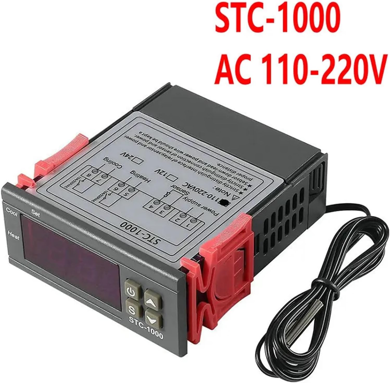
Image 1.1: Front and back view of the STC-1000 Digital Thermostat, showing the display, control buttons, and wiring diagram on the rear panel.
2. Safety Information
Please read and understand all safety instructions before installing or operating this device. Failure to follow these instructions may result in electric shock, fire, or damage to the product.
- Ensure the power supply voltage matches the specifications of the device (AC 110-220V for this model).
- All wiring should be performed by a qualified electrician to prevent electrical hazards.
- Do not operate the device in environments with excessive moisture, dust, or corrosive gases.
- Disconnect power before performing any maintenance or wiring changes.
- Keep the device away from children.
3. Product Overview
3.1 Key Features
- Switchable modes: Cool and Heat.
- Temperature control via setting value and difference value.
- Temperature calibration function.
- Refrigerating control output delay protection.
- Alarm for temperature exceeding limits or sensor error.
- NTC sensor included.
3.2 Component Identification (STC-1000)

Image 3.1: Front panel of the STC-1000, showing the Digital Display Window, Power Switch, UP Button, Setting Button, and Down Button.
- Digital Display Window: Shows current temperature and parameter values.
- Power Switch (U): Turns the device on/off.
- UP Button (Triangle Up): Increases values or navigates menu.
- Setting Button (S): Enters parameter setting mode or confirms selection.
- Down Button (Triangle Down): Decreases values or navigates menu.
3.3 Component Identification (STC-3000)
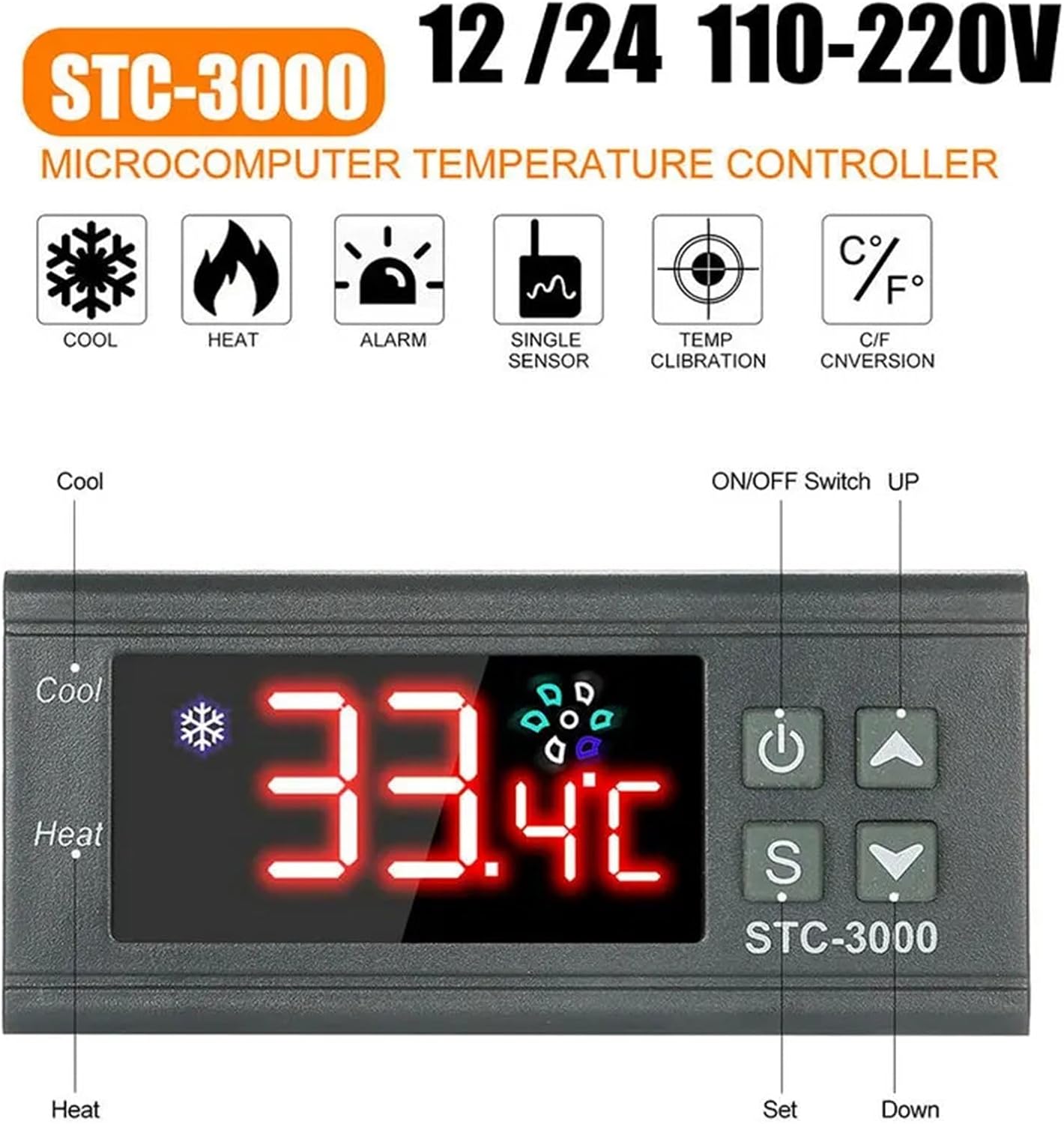
Image 3.2: Front panel of the STC-3000, showing the display, ON/OFF Switch, UP button, Setting button, and Down button, along with icons for Cool, Heat, Alarm, Single Sensor, Temp Calibration, and C/F Conversion.
The STC-3000 model features similar controls with additional icons indicating its capabilities, including Celsius/Fahrenheit conversion. The basic operation principles are largely consistent with the STC-1000.
3.4 Heat Dissipation

Image 3.3: Diagram showing the internal structure designed for effective heat dissipation, ensuring stable operation of the device.
The device is designed with internal structures to facilitate efficient heat dissipation, which is crucial for its long-term stability and performance.
4. Setup and Installation
4.1 Mounting
The STC-1000 is designed for panel mounting. The mounting size is 71x29mm. Ensure there is adequate space for ventilation around the device.
4.2 Wiring Diagram
Refer to the wiring diagram printed on the back of the device for correct connections. Ensure all connections are secure and insulated. The diagram typically includes connections for power supply, NTC sensor, heating output, and cooling output.
Image 4.1: Rear view of the STC-1000, showing the terminal block and printed wiring instructions. Ensure to distinguish between sensor, power supply, and load connections.
- Power Supply: Connect to AC 110-220V (or DC 12V/24V depending on model).
- NTC Sensor: Connect the temperature sensor.
- Cooling Output: Connect to your cooling device (e.g., fan, compressor).
- Heating Output: Connect to your heating device (e.g., heating element).
Important: Strictly distinguish between the sensor, power supply, and load connections. Power wires and load wires should be kept at a proper distance to avoid interference.
5. Operating Instructions
5.1 Checking Parameters
Under normal working status:
- Press the "UP" key to display the temperature setting value (F1).
- Press the "DOWN" key to display the difference value (F2).
5.2 Setting Parameters
To enter parameter modifying mode:
- Under normal working status, press and hold the "S" (Set) key for 3 seconds or more. The "Set" indicator light will turn on, and the screen will display the first menu code "F1".
- Use the "UP" or "DOWN" keys to navigate through the menu items (F1, F2, F3, F4).
- Press the "S" key to display the current value of the selected parameter.
- Use the "UP" or "DOWN" keys to adjust the value.
- Press the "S" key again to save the new value and exit the current parameter setting.
- To exit the parameter modifying mode, press the power key or wait for 10 seconds without any operation.
5.3 Menu Instruction Codes
| Code | Function | Set Range | Default |
|---|---|---|---|
| F1 | Temperature set value | -50.0~99.9°C | 10.0°C |
| F2 | Difference set value (Hysteresis) | 0.3~10.0°C | 0.5°C |
| F3 | Compressor delay time | 1~10 minutes | 3 minutes |
| F4 | Temperature calibration value | -10.0°C~10.0°C | 0°C |
Note on F2 (Difference set value): This is the hysteresis. For example, if F1 (set temperature) is 25°C and F2 is 0.5°C, the cooling will turn on at 25.5°C and turn off at 25°C. Heating will turn on at 24.5°C and turn off at 25°C.
Note on F3 (Compressor delay time): This setting protects the compressor by preventing rapid cycling. It delays the restart of the cooling output after it has turned off.
6. Maintenance
- Cleaning: Regularly wipe the display and casing with a soft, dry cloth. Do not use abrasive cleaners or solvents.
- Sensor Care: Ensure the NTC sensor is clean and free from debris. Avoid bending or damaging the sensor cable.
- Connections: Periodically check all wiring connections to ensure they are secure.
7. Troubleshooting
- Display shows "EE" or "HHH": This indicates a sensor error or the temperature exceeding the measurement range.
- Check if the NTC sensor is properly connected.
- Inspect the sensor cable for damage.
- Replace the sensor if it is faulty.
- Temperature not controlling:
- Verify the power supply to the controller and the connected heating/cooling devices.
- Check F1 (set temperature) and F2 (difference value) settings.
- Ensure the wiring for heating and cooling outputs is correct.
- Check if the compressor delay time (F3) is causing a temporary delay.
- Inaccurate temperature reading:
- Use F4 (temperature calibration) to adjust the reading if there's a known offset.
- Ensure the sensor is placed correctly and not affected by external heat sources or drafts.
8. Specifications
| Parameter | Value |
|---|---|
| Model | STC-1000 |
| Temperature Measuring Range | -50°C ~ 99°C |
| Resolution | 0.1°C |
| Accuracy | ±1°C (-50°C ~ 70°C) |
| Sensor Error Delay | 1 minute |
| Power Supply | AC 110-220V 50/60Hz (DC 12V, DC 24V, DC12-72V variants available) |
| Power Consumption | <3W |
| Sensor Type | NTC sensor (1PC) |
| Relay Contact Capacity (Cool) | 10A/220VAC |
| Relay Contact Capacity (Heat) | 10A/220VAC |
| Ambient Temperature | 0°C ~ 60°C |
| Storage Temperature | -30°C ~ 75°C |
| Relative Humidity | 20% ~ 85% (No condensate) |
| Sensor Length | 1.0m |
| Front Panel Size | 75x34.5mm |
| Product Size | 75x34.5x85 mm |
| Mounting Size | 71x29mm |
9. Warranty
This product is covered by a standard manufacturer's warranty against defects in materials and workmanship. Please refer to your purchase documentation for specific warranty terms and duration. The warranty does not cover damage caused by improper installation, misuse, unauthorized modifications, or natural disasters.
10. Support
For technical assistance, troubleshooting, or inquiries regarding your ESSISH STC-1000 Digital Thermostat, please contact your retailer or the manufacturer's customer support. Please have your product model and purchase details ready when contacting support.