
ESSISH AN8205C
ESSISH AN8205C Digital Multimeter User Manual
Model: AN8205C
1. Introduction
This manual provides detailed instructions for the safe and effective operation of the ESSISH AN8205C Digital Multimeter. This portable device is designed for measuring AC/DC voltage, AC/DC current, resistance, capacitance, frequency, temperature, diode, and continuity. Please read this manual thoroughly before use and keep it for future reference.
2. Safety Information
Always adhere to the following safety precautions to prevent personal injury or damage to the multimeter or equipment under test:
- Do not exceed the maximum input value specified for each range.
- Do not use the meter if it or the test leads appear damaged.
- Ensure the function switch is in the correct position for the measurement being performed.
- Be cautious when working with voltages above 30V AC RMS, 42V peak, or 60V DC, as they pose a shock hazard.
- Always disconnect the test leads from the circuit before changing the function or range.
- Remove batteries if the meter is not used for a long period.
- Do not operate the meter in explosive gas, vapor, or dust environments.
3. Product Features and Components
The AN8205C Digital Multimeter is equipped with various features for comprehensive electrical measurements. Familiarize yourself with the components shown below:

Figure 3.1: Labeled diagram of the AN8205C Digital Multimeter, highlighting key components such as the backlit screen, data hold key, range dial, AC/DC voltage/current inputs, resistance, temperature, diode/buzzer functions, and test lead jacks.

Figure 3.2: The AN8205C Digital Multimeter shown with its standard accessories, including the red and black test leads, a K-type thermocouple for temperature measurement, and the user manual.

Figure 3.3: Demonstration of the backlit bright screen feature. Pressing the "BACK LIGHT" key illuminates the display, making readings clear in low-light conditions.

Figure 3.4: Physical dimensions of the AN8205C Digital Multimeter, showing its compact size for portability and ease of handling.
4. Setup
4.1 Battery Installation
The AN8205C Multimeter typically uses a 9V battery (not always included). To install or replace the battery:
- Ensure the multimeter is turned off and test leads are disconnected.
- Locate the battery compartment cover on the back of the unit.
- Unscrew the retaining screw(s) and remove the cover.
- Insert a new 9V battery, observing the correct polarity (+ and -).
- Replace the battery cover and secure it with the screw(s).
4.2 Connecting Test Leads
For most measurements, connect the test leads as follows:
- Insert the black test lead into the "COM" (Common) jack.
- Insert the red test lead into the "VΩmA" jack for voltage, resistance, and small current measurements.
- For 10A current measurements, insert the red test lead into the "10ADC" jack.
5. Operating Instructions
Turn the rotary switch to the desired function and range. Connect the test leads to the circuit or component under test.
5.1 DC Voltage Measurement (V=)
- Connect the red lead to VΩmA jack and black lead to COM jack.
- Set the rotary switch to the desired DC Voltage range (e.g., 200mV, 2V, 20V, 200V, 600V).
- Connect the test leads across the DC voltage source.
- Read the voltage value on the display.
5.2 AC Voltage Measurement (V~)
- Connect the red lead to VΩmA jack and black lead to COM jack.
- Set the rotary switch to the desired AC Voltage range (e.g., 200V, 600V).
- Connect the test leads across the AC voltage source.
- Read the voltage value on the display.
5.3 DC Current Measurement (A=)
- Connect the red lead to VΩmA jack (for mA) or 10ADC jack (for 10A) and black lead to COM jack.
- Set the rotary switch to the desired DC Current range (e.g., 2m, 20m, 200m, 10A).
- Open the circuit and connect the meter in series with the load.
- Read the current value on the display.
5.4 Resistance Measurement (Ω)
- Connect the red lead to VΩmA jack and black lead to COM jack.
- Set the rotary switch to the desired Resistance range (e.g., 200Ω, 2kΩ, 20kΩ, 200kΩ, 2MΩ).
- Connect the test leads across the resistor or component.
- Read the resistance value on the display.
5.5 Temperature Measurement (°C)
The AN8205C supports temperature measurement using the included K-type thermocouple.
- Ensure the multimeter is off.
- Connect the thermocouple plug into the VΩmA and COM jacks, observing polarity.
- Set the rotary switch to the "°C" position.
- Place the thermocouple probe on or in the object whose temperature is to be measured.
- Read the temperature value on the display.

Figure 5.1: Example of temperature measurement using the AN8205C Digital Multimeter. The thermocouple is connected to the meter and immersed in a liquid to measure its temperature.
5.6 Diode Test
- Connect the red lead to VΩmA jack and black lead to COM jack.
- Set the rotary switch to the Diode symbol position.
- Connect the red lead to the anode and the black lead to the cathode of the diode.
- The display will show the forward voltage drop. Reverse the leads; the display should show "OL" (Open Loop) for a good diode.
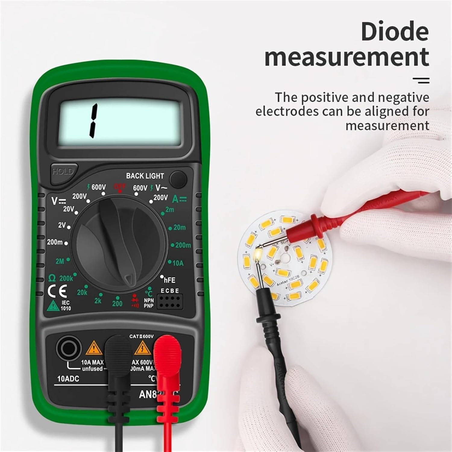
Figure 5.2: Illustration of a diode measurement being performed with the AN8205C Digital Multimeter. The test leads are connected to a circuit board to check the functionality of a diode.
5.7 Continuity Test
- Connect the red lead to VΩmA jack and black lead to COM jack.
- Set the rotary switch to the Continuity symbol position (often shared with Diode).
- Connect the test leads across the circuit or component.
- If continuity exists (resistance below a certain threshold), the buzzer will sound.
6. Maintenance
6.1 Cleaning
Wipe the case with a damp cloth and mild detergent. Do not use abrasives or solvents. Keep the terminals free of dirt or debris.
6.2 Battery Replacement
When the battery indicator appears on the display, replace the 9V battery as described in Section 4.1.
6.3 Fuse Replacement
If the current measurement function fails, the fuse may need replacement. Refer to the specifications for the correct fuse type and rating. Fuse replacement typically involves opening the back casing of the multimeter.
6.4 Storage
If the meter is not to be used for a long period, remove the battery to prevent leakage and store the meter in a dry, cool place.
7. Troubleshooting
- No display or dim display: Check battery. Replace if low.
- Incorrect readings:
- Ensure correct function and range are selected.
- Check test lead connections.
- Verify battery voltage.
- Current measurement not working: Check the fuse. Replace if blown.
- "OL" (Overload) displayed: The measured value exceeds the selected range. Switch to a higher range or check for an open circuit.
8. Specifications
| Parameter | Value |
|---|---|
| Brand | ESSISH |
| Model Number | AN8205C |
| DC Voltage | 200mV / 2V / 20V / 200V / 600V |
| AC Voltage | 200V / 600V |
| DC Current | 2mA / 20mA / 200mA / 10A |
| Resistance | 200Ω / 2kΩ / 20kΩ / 200kΩ / 2MΩ |
| Temperature | Yes (with K-type thermocouple) |
| Diode Test | Yes |
| Continuity Buzzer | Yes |
| Backlight | Yes |
| Power Supply | 9V Battery (e.g., 6F22) |
| Dimensions | 142.8mm x 71.5mm x 34.6mm (approx.) |
| Weight | Approx. 50 Grams (without battery) |
| Safety Rating | CAT II 600V |
9. Warranty and Support
For warranty information or technical support, please contact ESSISH customer service through the retailer where the product was purchased. Keep your purchase receipt as proof of purchase.
For further assistance, you may refer to the official ESSISH website or contact their support channels directly.
Related documentsAN8205C


Ask a question about this manual
Ask about setup, troubleshooting, compatibility, parts, safety, or missing instructions. Manuals+ will review the question and use this page’s manual context to help answer it.