1. Introduction and Overview
This manual provides detailed instructions for the installation, operation, and maintenance of the Generic MSI MS-S0981 H87 LGA1150 DDR3 Server Motherboard. Designed for server applications, this motherboard supports Intel LGA1150 processors and DDR3 memory, offering robust performance and connectivity for various computing needs.
Please read this manual thoroughly before attempting any installation or configuration to ensure proper setup and prevent damage to the components.
2. Safety Information
- Always disconnect the power supply from the wall outlet before installing or removing any components.
- Wear an anti-static wrist strap or frequently touch a grounded metal object to discharge static electricity before handling the motherboard or other components.
- Handle the motherboard by its edges to avoid touching sensitive components.
- Ensure proper ventilation within the server chassis to prevent overheating.
- Keep the motherboard away from moisture and extreme temperatures.
3. Package Contents
Verify that all items are present and in good condition upon opening the package. If any items are missing or damaged, contact your vendor immediately.
- Generic MSI MS-S0981 H87 LGA1150 DDR3 Server Motherboard
- User Manual (this document)
- SATA Data Cables (quantity may vary)
- I/O Shield
4. Motherboard Layout and Components
Familiarize yourself with the various components and connectors on the motherboard before installation.
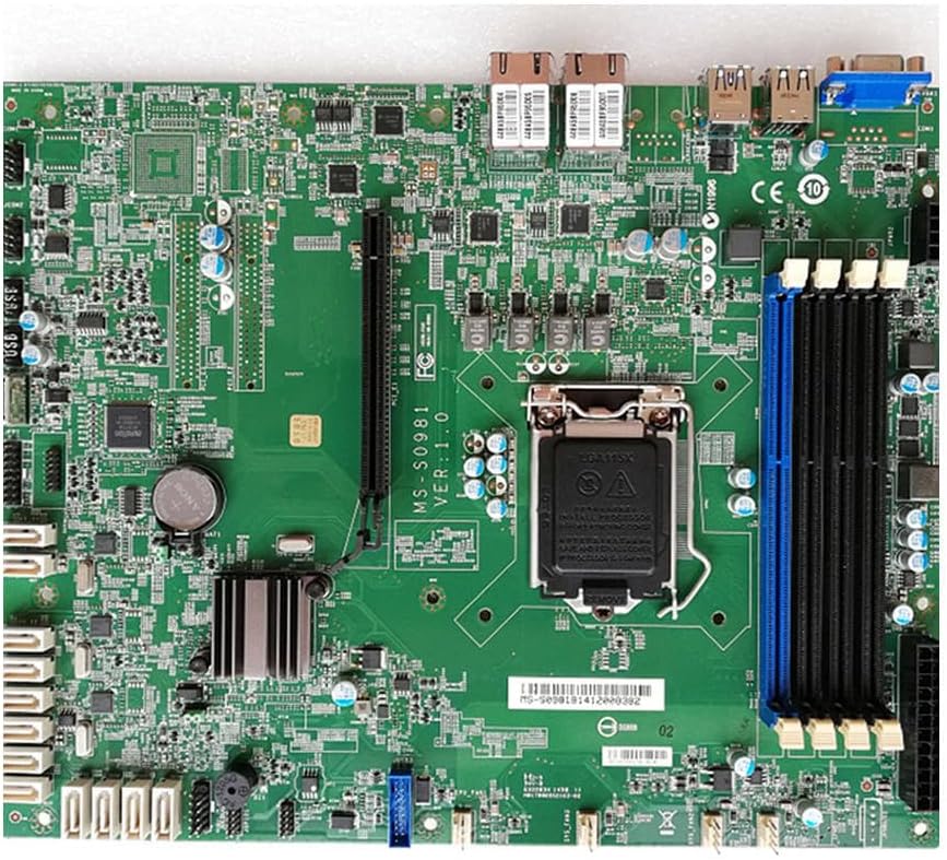
Figure 4.1: Top-down view of the MS-S0981 motherboard, showing the LGA1150 CPU socket, DDR3 DIMM slots, PCIe slots, SATA ports, and various headers.
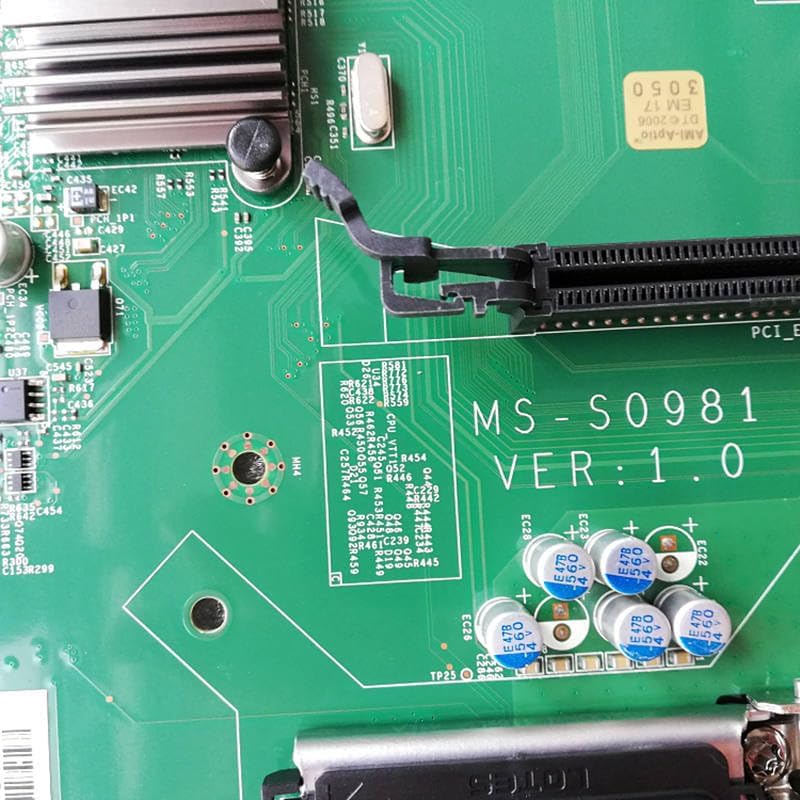
Figure 4.2: Detail of the motherboard showing the 'MS-S0981 VER:1.0' marking and surrounding capacitors, indicating the model and revision.

Figure 4.3: Angled view highlighting the rear I/O panel with USB ports, LAN ports, and video outputs, along with the PCIe expansion slots.
Key Components:
- LGA1150 CPU Socket: Supports Intel 4th generation Core i7/i5/i3/Pentium/Celeron processors.
- DDR3 DIMM Slots: Multiple slots for DDR3 memory modules.
- PCIe Expansion Slots: For graphics cards, network cards, and other expansion devices.
- SATA3 Ports: High-speed connectors for storage devices like SSDs and HDDs.
- Rear I/O Panel: Includes USB ports, LAN ports, and video output (VGA).
- Front Panel Headers: Connectors for power button, reset button, USB ports, and audio jacks on the chassis.
5. Setup and Installation
5.1 Pre-installation Checklist
- Ensure you have a compatible CPU (LGA1150), DDR3 RAM, and a power supply.
- Prepare a clean, well-lit workspace.
- Gather necessary tools: Phillips head screwdriver, thermal paste.
5.2 CPU Installation
- Gently lift the CPU socket lever and open the metal load plate.
- Align the CPU with the socket, ensuring the golden triangle on the CPU matches the marking on the socket. Do not force the CPU into the socket.
- Close the load plate and press down the lever until it locks into place.
- Apply a thin, even layer of thermal paste to the top of the CPU.
- Install the CPU cooler according to its manufacturer's instructions, ensuring it makes firm contact with the CPU.
5.3 RAM Installation
- Open the clips at both ends of the DDR3 DIMM slots.
- Align the notch on the memory module with the key in the DIMM slot.
- Insert the memory module firmly into the slot until the clips snap into place. Ensure both clips are closed.
- For optimal performance, install memory modules in matching pairs for dual-channel operation, referring to the motherboard's silkscreen for recommended slots.
5.4 Storage Device Installation (SATA)
- Connect one end of a SATA data cable to a SATA3 port on the motherboard.
- Connect the other end of the SATA data cable to your SSD or HDD.
- Connect a SATA power cable from your power supply to the storage device.
5.5 Power Supply Connections
- Connect the 24-pin ATX power connector from your power supply to the main power header on the motherboard.
- Connect the 8-pin EPS (CPU) power connector from your power supply to the CPU power header near the CPU socket.
5.6 Front Panel and Peripheral Connections
- Connect the front panel headers (power switch, reset switch, HDD LED, power LED) to their respective pins on the motherboard, observing polarity.
- Connect front panel USB and audio headers.
- Install the I/O shield into the chassis opening before mounting the motherboard.
- Secure the motherboard to the chassis using appropriate standoffs and screws.
6. Operating Instructions
6.1 Initial Boot and BIOS/UEFI Setup
- After assembling all components, connect a monitor, keyboard, and mouse.
- Power on the system. During the initial boot sequence, press the designated key (usually DEL or F2) repeatedly to enter the BIOS/UEFI setup utility.
- In the BIOS/UEFI, verify that all installed components (CPU, RAM, storage) are detected correctly.
- Configure boot order to prioritize your operating system installation media (USB drive or optical drive).
- Save changes and exit the BIOS/UEFI. The system will restart.
6.2 Operating System Installation
Follow the instructions provided with your chosen operating system (e.g., Windows Server, Linux distribution) to complete the installation process. Ensure all necessary drivers for the motherboard's chipset, network, and other integrated components are installed after the OS is set up.
7. Maintenance
7.1 Cleaning
- Regularly clean dust from the motherboard and cooling components using compressed air.
- Ensure the system is powered off and unplugged before cleaning.
- Avoid using liquid cleaners directly on components.
7.2 BIOS/Firmware Updates
Periodically check the manufacturer's website for updated BIOS/firmware versions. Updates can improve stability, compatibility, and performance. Follow the specific instructions provided with the update utility carefully to avoid damaging the motherboard.
8. Troubleshooting
8.1 Common Issues and Solutions
- No Power: Check all power connections (24-pin ATX, 8-pin EPS, power button header). Ensure the power supply is switched on.
- No Display (No POST): Verify that the CPU, RAM, and graphics card (if dedicated) are correctly seated. Try booting with only one RAM stick. Check monitor connection.
- System Instability/Crashes: Check CPU and GPU temperatures. Ensure RAM is compatible and properly installed. Update drivers and BIOS/firmware.
- Storage Not Detected: Verify SATA data and power cable connections. Check BIOS/UEFI settings to ensure SATA ports are enabled.
8.2 Clear CMOS
If the system experiences boot issues due to incorrect BIOS settings, you can clear the CMOS to restore default settings. Locate the 'Clear CMOS' jumper or button on the motherboard (refer to the layout diagram) or remove the CMOS battery for a few minutes while the system is unplugged.
9. Specifications
| Feature | Specification |
|---|---|
| Brand | Generic |
| Model | MS-S0981 |
| Version | V:1.0 |
| CPU Socket | LGA1150 |
| Chipset | H87 |
| Memory Type | DDR3 |
| Storage Interface | SATA3 |
| Part Number | LlMER_GBFG__18751 |
| First Available | Jan. 17 2024 |
10. Warranty Information
This product is typically covered by a warranty provided by the seller at the time of purchase. Please refer to your purchase documentation, invoice, or the seller's terms and conditions for specific warranty duration and coverage details. Keep your proof of purchase for any warranty claims.
11. Support
For technical assistance, troubleshooting beyond the scope of this manual, or warranty inquiries, please contact the vendor or retailer from whom you purchased this motherboard. They will be able to provide specific support related to your product.