1. Introduction
This manual provides essential information for the safe and effective operation, setup, and maintenance of your KIRANDY CP-800S Double Circuit Manual Hydraulic Pump. This two-way pump is designed for various hydraulic operations, including lifting, bending, straightening, shearing, riveting, and disassembly, when used with compatible hydraulic cylinders or tools.
Please read this manual thoroughly before operating the pump and retain it for future reference.
2. Safety Instructions
- Always wear appropriate personal protective equipment (PPE), including safety glasses and gloves, when operating hydraulic equipment.
- Ensure the pump is placed on a stable, level surface before operation.
- Do not exceed the maximum rated pressure of 70MPa for high pressure and 20MPa for low pressure.
- Regularly inspect hydraulic hoses and connections for damage or leaks. Replace any damaged components immediately.
- Keep hands and clothing clear of moving parts and pressurized components.
- Never attempt to repair or modify the pump while it is under pressure.
- Use only recommended hydraulic oil. Mixing different types of hydraulic oil can cause system damage.
- Release pressure slowly and carefully after operation.
3. Product Overview
The KIRANDY CP-800S is a robust manual hydraulic pump designed for high-pressure applications. It features a double circuit system for efficient operation.
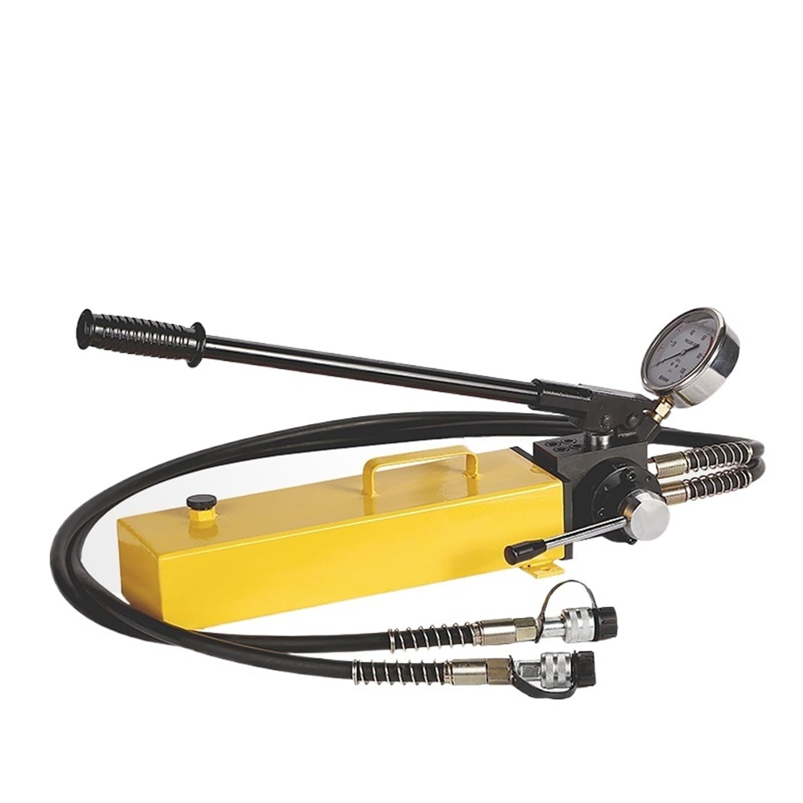
Figure 3.1: Overall view of the KIRANDY CP-800S Double Circuit Manual Hydraulic Pump, highlighting its key features and specifications.

Figure 3.2: Diagram illustrating the main components of the CP-800S pump, including the shock-resistant pressure gauge, air release valve (fuel filler), and manual pressure relief valve.
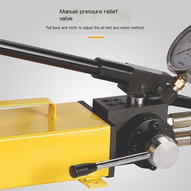
Figure 3.3: Close-up view of the manual pressure relief valve. This lever is used to adjust the oil inlet and return method by pulling it back and forth.

Figure 3.4: Detailed view of the shockproof pressure gauge, which provides real-time observation of pressure changes and is designed for non-explosive pump operation.

Figure 3.5: Close-up of the dual hydraulic oil pipe connectors, featuring a one-inlet and one-outlet dual mode design for efficient hydraulic fluid transfer.

Figure 3.6: Close-up of the air release valve, also serving as the fuel filler. This nut must be loosened when a switch indicating use is present at the rear of the pump.
4. Specifications
| Feature | Specification |
|---|---|
| Model | CP-800S |
| High Pressure | 70 MPa |
| Low Pressure | 20 MPa |
| High Pressure Oil Volume | 2.3 CC |
| Low Pressure Oil Volume | 13 CC |
| Oil Storage Capacity | 3000 CC |
| Standard Oil Pipe Length | 1.9 meters |
| Weight | 21 kg / 22 kg |
| Manufacturer | SENMIAO-UK |
| Part Number | INQBIEACN-CP-800SMANUALPUMP+METER |
5. Setup
- Unpacking: Carefully remove the pump and all accessories from the packaging. Inspect for any shipping damage.
- Placement: Position the pump on a firm, level, and stable surface to prevent tipping during operation.
- Hydraulic Oil Check: Verify that the oil reservoir contains sufficient hydraulic oil. If necessary, add recommended hydraulic oil through the air release valve/fuel filler (refer to Figure 3.6).
- Connect Hoses: Connect the standard oil pipes to the appropriate hydraulic tool or cylinder. Ensure all connections are tight and secure to prevent leaks. The CP-800S uses a dual hydraulic oil pipe system (refer to Figure 3.5).
- Air Release Valve: Before operation, loosen the air release valve (refer to Figure 3.6) to allow air to escape from the reservoir. This prevents vacuum formation and ensures proper oil flow. Tighten it before transport or storage.
6. Operating Instructions
- Preparation: Ensure the hydraulic tool is correctly attached and the air release valve is loosened.
- Pumping: Operate the pump handle with steady, full strokes. The pump will initially operate in low-pressure mode, moving a larger volume of oil quickly.
- High Pressure Activation: As resistance increases (e.g., the hydraulic tool encounters a load), the pump will automatically switch to high-pressure mode, delivering less oil volume but at a higher pressure (up to 70MPa).
- Monitoring Pressure: Observe the shockproof pressure gauge (refer to Figure 3.4) to monitor the hydraulic pressure. Do not exceed the maximum rated pressure of the pump or the connected tool.
- Releasing Pressure: To release pressure and retract the hydraulic tool, slowly pull back the manual pressure relief valve lever (refer to Figure 3.3). This will allow the hydraulic fluid to return to the reservoir.
- Completion: Once the operation is complete and pressure is fully released, tighten the air release valve before moving or storing the pump.
7. Maintenance
- Oil Level: Regularly check the hydraulic oil level. Maintain the oil level between the minimum and maximum marks on the reservoir.
- Oil Replacement: Replace hydraulic oil periodically, typically every 6-12 months or after extensive use, to ensure optimal performance and prevent contamination. Use only recommended hydraulic oil.
- Cleaning: Keep the pump clean and free from dirt, dust, and debris. Wipe down the exterior with a clean cloth.
- Hose Inspection: Inspect hydraulic hoses and fittings for wear, cracks, or leaks before each use. Replace damaged hoses immediately.
- Storage: Store the pump in a clean, dry environment, protected from extreme temperatures and moisture. Ensure all pressure is released and the air release valve is tightened before storage.
8. Troubleshooting
| Problem | Possible Cause | Solution |
|---|---|---|
| Pump not building pressure | Low oil level Air in the system Pressure relief valve open/leaking | Check and refill oil Loosen air release valve, pump to bleed air, then tighten Check relief valve for proper closure |
| Oil leakage | Loose connections Damaged seals/hoses | Tighten all connections Inspect and replace damaged components |
| Pump handle feels spongy | Air in the system | Loosen air release valve, pump to bleed air, then tighten |
| Hydraulic tool not retracting | Pressure not fully released Return line blocked | Ensure manual pressure relief valve is fully open Check return hose for kinks or obstructions |
9. Warranty and Support
For warranty information or technical support regarding your KIRANDY CP-800S Double Circuit Manual Hydraulic Pump, please refer to the documentation provided at the time of purchase or contact your retailer. Keep your purchase receipt as proof of purchase.