DONGKER 6-Digit Calculator Soldering DIY Kit
Instruction Manual (Model: GY21299-3ABHIC)
1. Introduction
This manual provides comprehensive instructions for assembling and operating your DONGKER 6-Digit Calculator Soldering DIY Kit. This kit is designed to enhance soldering skills and deepen understanding of electronic components, making it an ideal educational project for students and hobbyists. Upon successful completion, you will have a functional desktop calculator.

Image: A person engaged in soldering, with the DONGKER DIY Calculator kit visible on a workbench, illustrating the hands-on learning experience.
2. Safety Information
Please read and understand all safety precautions before beginning assembly. Improper use of soldering equipment can cause injury or damage.
- Always work in a well-ventilated area to avoid inhaling solder fumes.
- Wear appropriate eye protection (safety glasses) to protect against splashes or flying debris.
- Use a soldering iron stand to prevent accidental burns.
- Ensure the soldering iron is unplugged and cooled before storing.
- Keep all components and tools out of reach of small children.
- This kit is recommended for ages 14 and above. Adult supervision is advised for younger users.
3. Package Contents
Verify that all components listed below are present in your kit before starting assembly.

Image: Overview of all components included in the kit, such as the PCB, acrylic housing, display, buttons, and various electronic parts.
- Main PCB (Printed Circuit Board)
- Acrylic Casing Parts (Top, Bottom, Button Grid)
- 6-Digit 7-Segment Display Modules
- Tactile Buttons (various colors)
- Integrated Circuits (ICs) and Sockets
- Resistors, Capacitors, Diodes
- USB Power Connector
- CR2032 Button Cell Holder (Battery not always included)
- Screws and Standoffs
4. Assembly Instructions (Setup)
This kit requires basic electronic theoretical knowledge and soldering skills. Patience is needed, especially for assembling the keys. All components have clearly assigned and marked connectors on the PCB.
- Prepare the PCB: Identify all soldering points and component placements as indicated on the PCB.
- Solder Smaller Components First: Begin by soldering the lowest profile components such as resistors, diodes, and IC sockets (if applicable). Ensure correct orientation for polarized components (diodes, ICs).
- Install ICs: If using sockets, insert the ICs into their respective sockets after soldering the sockets to the PCB. Ensure correct orientation (notch/dot alignment).
- Solder Display Modules: Attach the 6-digit 7-segment display modules to their designated positions.
- Solder Buttons: Carefully solder all tactile buttons. This step requires patience to ensure they are flush and functional.
- Solder Power Connectors: Solder the USB power connector and the button cell holder.
- Assemble Acrylic Casing: Once all soldering is complete and verified, assemble the acrylic casing around the PCB using the provided screws and standoffs. Ensure the button grid aligns perfectly with the soldered buttons.

Image: Detailed view of the transparent keycaps, USB power input, and button cell power input, highlighting key assembly points.
5. Operating Instructions
5.1 Powering On
The calculator can be powered by either a USB cable (not included) or a CR2032 button cell battery (not always included). Do not supply power simultaneously from both sources.
- USB Power: Connect a standard Micro USB cable to the calculator and a 5V power source.
- Battery Power: Insert a CR2032 button cell battery into the battery holder, ensuring correct polarity.
To turn on the calculator, briefly press the ON/C button. To enter sleep mode, long-press the ON/C button.
5.2 Basic Arithmetic Operations
The calculator supports basic arithmetic operations with decimals and negative numbers, and continuous calculations.
- Enter numbers using the numeric keypad.
- Use the +, -, ×, ÷ buttons for addition, subtraction, multiplication, and division.
- Press = to display the result.
- Press ON/C to clear the current entry or calculation.
5.3 Resistance Value Measurement Mode
The calculator can measure the resistance value of four or five-band resistors by inputting the color codes.
- Long-press the MODE button to switch to resistance measurement mode. The digital display will show [ - - - - - - ].
- Enter the color bands of the resistor using the corresponding buttons.
- Press the = button to obtain the resistance value.
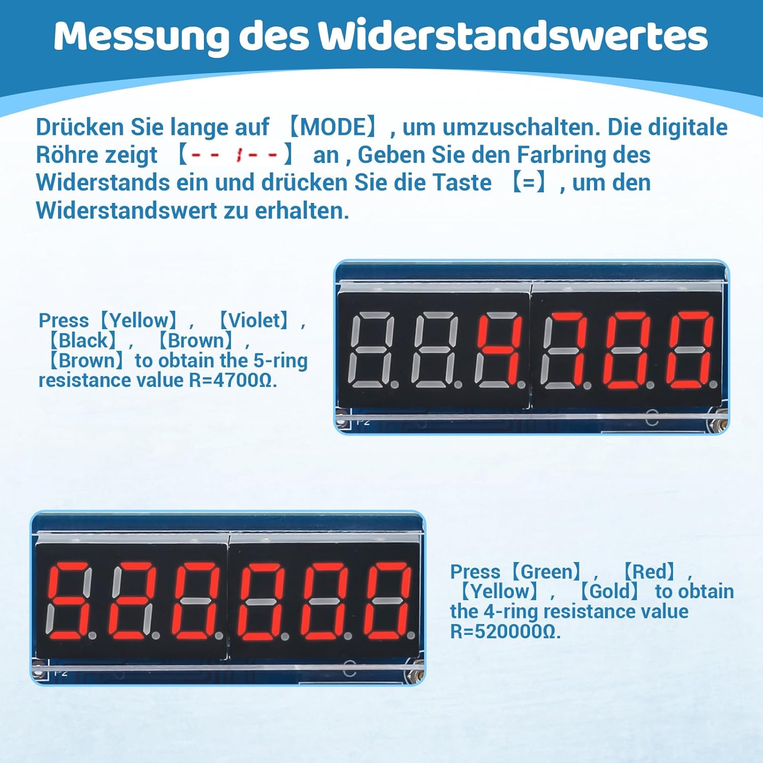
Image: Examples of resistance value measurement, showing input color codes and calculated resistance values on the display.

Image: Visual guide to the calculator's display modes and button functionalities, including handling of calculation results.
6. Maintenance
- Cleaning: Use a soft, dry cloth to clean the acrylic casing. Avoid abrasive cleaners or solvents.
- Battery Replacement: If using battery power, replace the CR2032 button cell when the display dims or the calculator stops functioning. Ensure correct polarity.
- Storage: Store the calculator in a dry, cool place away from direct sunlight and extreme temperatures.
7. Troubleshooting
| Problem | Possible Cause | Solution |
|---|---|---|
| Calculator does not power on. | No power source connected or battery depleted/incorrectly inserted. | Connect USB power or replace/reinsert CR2032 battery with correct polarity. Ensure only one power source is connected. |
| Buttons are unresponsive or sticky. | Poor soldering connection for buttons or misalignment of acrylic button grid. | Check soldering points for cold joints or bridges. Re-align the acrylic casing if necessary. |
| Incorrect calculation results. | Component values incorrect or soldering errors on ICs/resistors. | Verify all components are correctly placed and soldered according to the schematic. Check IC orientation. |
| Display shows garbled characters or nothing. | Display module not soldered correctly or IC issue. | Inspect display module soldering. Ensure ICs are seated properly in sockets. |
8. Specifications
- Model Number: GY21299-3ABHIC
- Brand: DONGKER
- Display: 6-Digit 7-Segment LED
- Power Source: USB 5V or CR2032 Button Cell Battery
- Functions: Basic arithmetic (addition, subtraction, multiplication, division), decimal and negative numbers, continuous calculation, 4/5-band resistor value measurement.
- Dimensions (Assembled): Approximately 16 x 14 x 6 cm (6.3 x 5.5 x 2.4 inches)
- Weight: Approximately 150 grams (0.33 lbs)
- Recommended Age: 14 - 80 years
- Material: PCB, Acrylic, Electronic Components

Image: Visual representation of the calculator's dimensions and key features, including power options and display type.
9. Schematic Diagram
For advanced users or troubleshooting, the schematic diagram provides a detailed view of the circuit connections.
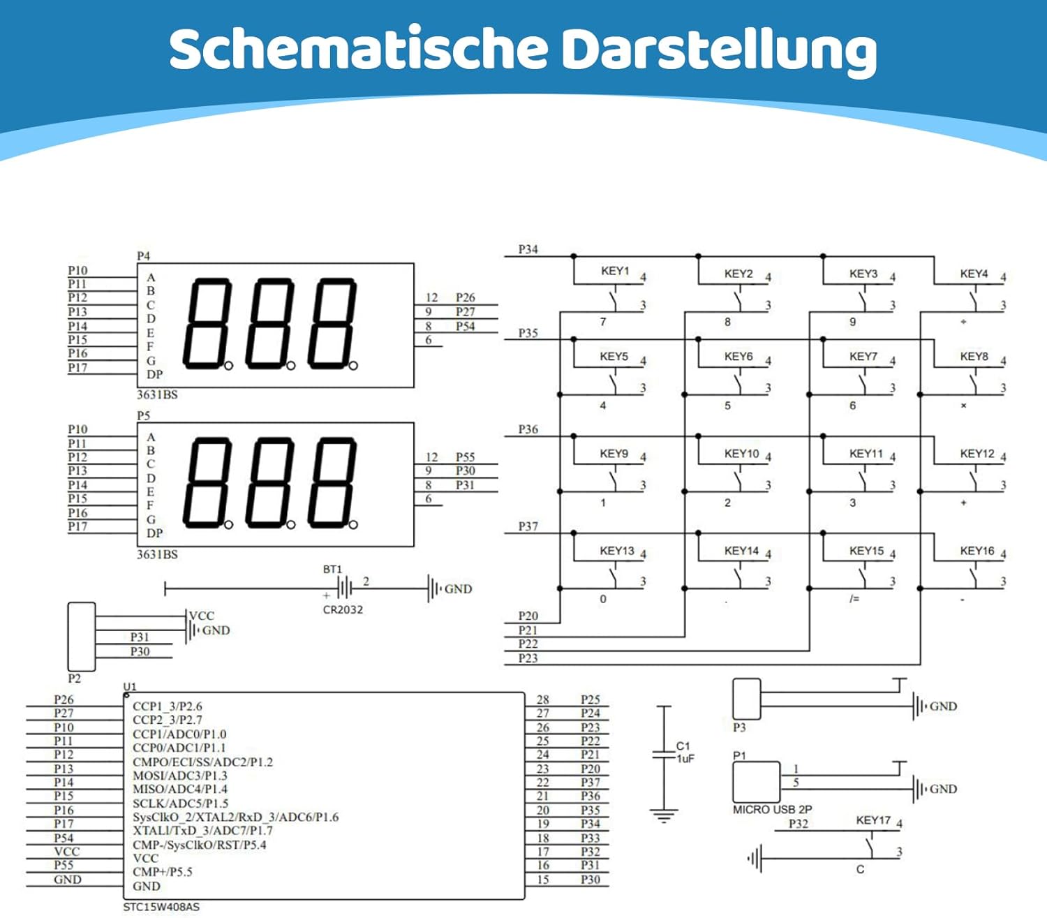
Image: Full schematic diagram of the calculator's internal circuitry.
10. Warranty and Support
This product is a DIY kit, and its functionality largely depends on the user's assembly and soldering skills. DONGKER provides support for missing or defective components upon receipt. For assembly assistance or troubleshooting, please refer to the detailed instructions provided in this manual.
For further inquiries, please contact your retailer or the manufacturer directly.