Introduction
This manual provides detailed instructions for the installation, operation, and maintenance of the ArecaIoT KWL-01-2PT 2 Channels PT100 Sensor RS485 Modbus Output Temperature Acquisition Module. This module is designed for industrial applications requiring precise temperature measurement using PT100 sensors and data transmission via RS485 Modbus protocol.
The KWL-01-2PT module features two independent channels for PT100 sensor input, providing isolated RS485 Modbus output for reliable data acquisition. It operates on a 6-36V DC power supply and offers high temperature accuracy.
Key Features
- Input: 2 channels for PT100 temperature sensors.
- Output: Isolated RS485 Modbus communication.
- Power Supply: Wide range 6-36V DC.
- Temperature Range: -200°C to 850°C.
- Temperature Accuracy: ±0.3°C.
- Communication Protection: Self-restoring fuse, anti-reverse diode, TVS diode for overvoltage, overcurrent, and anti-reverse connection protection.
- Isolation: Measurement isolation (3000V) and communication isolation for enhanced reliability.
- Microprocessor: High-speed 32-bit microprocessor for efficient data processing.
Technical Specifications
| Parameter | Value |
|---|---|
| Model | KWL-01-2PT |
| Supply Power | 6-36V DC |
| Input Channels | 2 channels PT100 |
| Output Interface | Isolated RS485 (Modbus) |
| Temperature Range | -200°C to 850°C |
| Temperature Accuracy | ±0.3°C |
| Power Consumption | <200mW |
| Acquisition Rate | 100KHz/channel |
| Data Update Rate | 10Hz/channel |
| Sensor Type | 2 or 3 wires PT100 |
| Baud Rate | 1200-115200 (default 9600) |
| Error Alarm | Sensor disconnects detection |
| Dimensions | 82mm x 54mm x 32mm |
Note: Specifications are subject to change without prior notice.
Setup and Wiring
Proper wiring is crucial for the correct operation and safety of the module. Ensure all connections are secure before applying power.
1. Module Overview and Dimensions
The KWL-01-2PT module features clearly labeled terminals for power, RS485 communication, and PT100 sensor inputs.
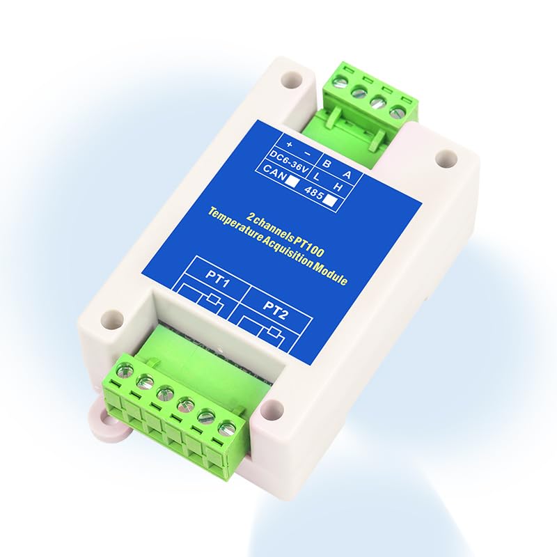
Image: Top view of the KWL-01-2PT module showing power, RS485, and PT100 input terminals. The module is white with a blue label.

Image: The KWL-01-2PT module with text overlay indicating "2 channels PT100 RS485 output". This highlights the primary function of the device.
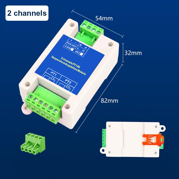
Image: The KWL-01-2PT module with dimensions labeled: 82mm length, 54mm width, and 32mm height. This provides physical size information for installation planning.
2. Power Supply Connection
Connect the DC power supply to the terminals labeled DC6-36V. Observe polarity:
- +: Positive terminal of the DC power supply.
- -: Negative terminal of the DC power supply.
The module supports a wide input voltage range of 6-36V DC.
3. RS485 Communication Wiring
Connect the RS485 communication lines to the terminals labeled A and B.
- A: RS485 Data A line.
- B: RS485 Data B line.
Ensure proper termination resistors are used in the RS485 network if required by your system design.
4. PT100 Sensor Wiring
The module supports two PT100 sensors (PT1 and PT2). PT100 sensors can be connected in either 2-wire or 3-wire configurations. The module automatically detects the wiring type.

Image: Wiring diagram illustrating 2-wire and 3-wire PT100 sensor connections to the module. For 2-wire, connect the two sensor wires to the first two terminals. For 3-wire, connect the two identical wires to the first two terminals and the third wire to the third terminal.
- 2-wire PT100: Connect the two wires of the PT100 sensor to the first two terminals of the respective PT input (e.g., PT1).
- 3-wire PT100: Connect the two identical wires (usually red) to the first two terminals and the third wire (usually white) to the third terminal of the respective PT input. This configuration provides better accuracy by compensating for lead wire resistance.
Ensure the PT100 sensors are correctly rated for the temperature range of your application.
Operation
The KWL-01-2PT module communicates via the Modbus RTU protocol over an RS485 interface. After successful wiring and power-up, the module will begin acquiring temperature data from the connected PT100 sensors.
1. Modbus Communication
The module acts as a Modbus slave device. A Modbus master (e.g., PLC, HMI, or computer with Modbus software) is required to read temperature data from the module.
- Baud Rate: Configurable from 1200 to 115200 bps, with a default of 9600 bps. Ensure the master device's baud rate matches the module's setting.
- Data Format: Typically 8 data bits, no parity, 1 stop bit (8N1) or 8 data bits, even/odd parity, 1 stop bit (8E1/8O1). Refer to the specific Modbus register map for detailed communication parameters.
- Slave Address: Each module on an RS485 bus must have a unique slave address. The default address is usually 1. Consult the module's specific Modbus register map for details on how to configure the address and read data.
The module provides isolated RS485 communication, enhancing noise immunity and reliability in industrial environments.
2. Reading Temperature Data
Temperature values are typically stored in Modbus holding registers or input registers. The Modbus master sends read commands to the module's slave address to retrieve the current temperature readings from PT1 and PT2.
The temperature data is usually represented as an integer value that needs to be scaled (e.g., divided by 10 or 100) to obtain the actual temperature in degrees Celsius (°C). Refer to the module's Modbus register map for the exact register addresses and scaling factors.
3. Error Indication
The module features an error alarm for sensor disconnects. If a PT100 sensor is disconnected or faulty, the module will indicate this status, typically by setting a specific bit in a Modbus status register or through an LED indicator (if present).

Image: Diagram illustrating the module's internal protection features, including measurement isolation, communication isolation, power input protection, wide voltage input, communication protection, communication power indication, and the 32-bit microprocessor. These features contribute to stable, safe, and durable operation.
Maintenance
The KWL-01-2PT module is designed for reliable operation with minimal maintenance. However, periodic checks can help ensure its longevity and accuracy.
- Cleaning: Keep the module clean and free from dust and debris. Use a soft, dry cloth for cleaning. Do not use harsh chemicals or solvents.
- Environmental Conditions: Ensure the module is operated within its specified environmental conditions (temperature, humidity) to prevent damage.
- Wiring Inspection: Periodically inspect all wiring connections for tightness and signs of corrosion or damage. Loose connections can lead to intermittent operation or inaccurate readings.
- Sensor Calibration: While the module itself is highly accurate, the PT100 sensors may require periodic calibration depending on the application's requirements and industry standards. Refer to your PT100 sensor manufacturer's guidelines for calibration procedures.
- Firmware Updates: Check the manufacturer's website for any available firmware updates that may improve performance or add new features. Follow the provided instructions carefully for any update procedures.
Troubleshooting
This section addresses common issues you might encounter with the KWL-01-2PT module.
No Power Indication / Module Not Responding
- Check Power Supply: Verify that the 6-36V DC power supply is connected correctly and providing the specified voltage. Ensure polarity is correct (+ to +, - to -).
- Check Wiring: Inspect power supply wiring for loose connections or breaks.
- Internal Fuse: The module has a self-restoring fuse. If an overcurrent event occurred, disconnect power, wait a few minutes, and then reapply. If the issue persists, there might be a short circuit in the wiring or a faulty component.
Incorrect or Unstable Temperature Readings
- Sensor Connection: Ensure PT100 sensors are securely connected to the correct terminals. Verify 2-wire or 3-wire configuration is correct and wires are not swapped.
- Sensor Integrity: Check the PT100 sensor for damage or open circuits. A disconnected sensor will trigger an error alarm.
- Environmental Interference: Ensure the sensor and module are not exposed to strong electromagnetic interference (EMI) or rapid temperature fluctuations that could affect readings.
- Scaling Factor: Confirm that the Modbus master is applying the correct scaling factor to the raw temperature data read from the module.
Modbus Communication Errors
- Baud Rate and Data Format: Verify that the Modbus master's baud rate, parity, and stop bits match the module's settings (default 9600, 8N1).
- Slave Address: Ensure the Modbus master is addressing the correct slave ID of the module. Each module on the bus must have a unique address.
- RS485 Wiring: Check RS485 A and B lines for correct polarity and secure connections. Ensure termination resistors are correctly placed if needed.
- Bus Conflicts: If multiple devices are on the RS485 bus, ensure there are no address conflicts or communication timing issues.
- Modbus Register Map: Confirm that the Modbus master is attempting to read from the correct register addresses as specified in the module's Modbus register map.
Module Overheating
- Ventilation: Ensure adequate ventilation around the module, especially if installed in an enclosure.
- Ambient Temperature: Verify that the ambient operating temperature is within the specified range.
- Power Supply: Check if the power supply voltage is within the 6-36V DC range. Overvoltage can cause excessive heat.
Warranty and Support
ArecaIoT products are manufactured to high-quality standards. For specific warranty information, please refer to the documentation included with your purchase or contact ArecaIoT customer support.
For technical assistance, troubleshooting, or inquiries regarding your KWL-01-2PT module, please contact your vendor or ArecaIoT customer support through their official channels. When contacting support, please have your module model number (KWL-01-2PT) and a detailed description of the issue ready.
Manufacturer: ComWinTop
Brand: ArecaIoT

Image: Label showing manufacturer details (ComWinTop), address, contact information, and CE REP (Consulting Business Management) details. This information is useful for support and compliance.