1. Introduction
This instruction manual provides essential information for the safe and efficient installation, operation, and maintenance of your YAOSHENG 200W PoE Injector. This device is designed to provide Power over Ethernet (PoE) to standard Starlink models, ensuring reliable network connectivity and power delivery with comprehensive protection features.
2. Safety Information
Please read and understand all safety instructions before operating this device. Failure to follow these instructions may result in electric shock, fire, or damage to the product.
- Power Source: Ensure the input voltage and current match the specifications of the PoE injector (48-57 VDC, 4A). Using an incorrect power source can damage the device and connected equipment.
- Grounding: For surge protection, proper grounding is required. Connect the grounding wire to a reliable earth ground.
- Environment: Do not expose the device to water, moisture, or extreme temperatures. Operate within specified environmental conditions.
- Ventilation: Ensure adequate ventilation around the device to prevent overheating.
- Servicing: Do not attempt to open or repair the device yourself. Refer all servicing to qualified personnel.
3. Package Contents
Verify that all items are present in your package:
- 1 x YAOSHENG 200W GigE PoE Injector (Model: YSNEPPU20010A)
4. Product Features
The YAOSHENG 200W PoE Injector is equipped with advanced protection and performance features:
- Input over and under voltage protection.
- Reverse polarity protection.
- Over-current and short-circuit protection.
- Overheating protection.
- Working state LED indication.
5. Product Overview
Familiarize yourself with the components and design of your PoE injector.

Figure 1: Front view of the YAOSHENG 200W PoE Injector, showing the LAN and PoE ports, DC input terminals, and product label with model number YSNEPPU20010A. For detailed specifications, scan the QR code or visit yaosheng.io.
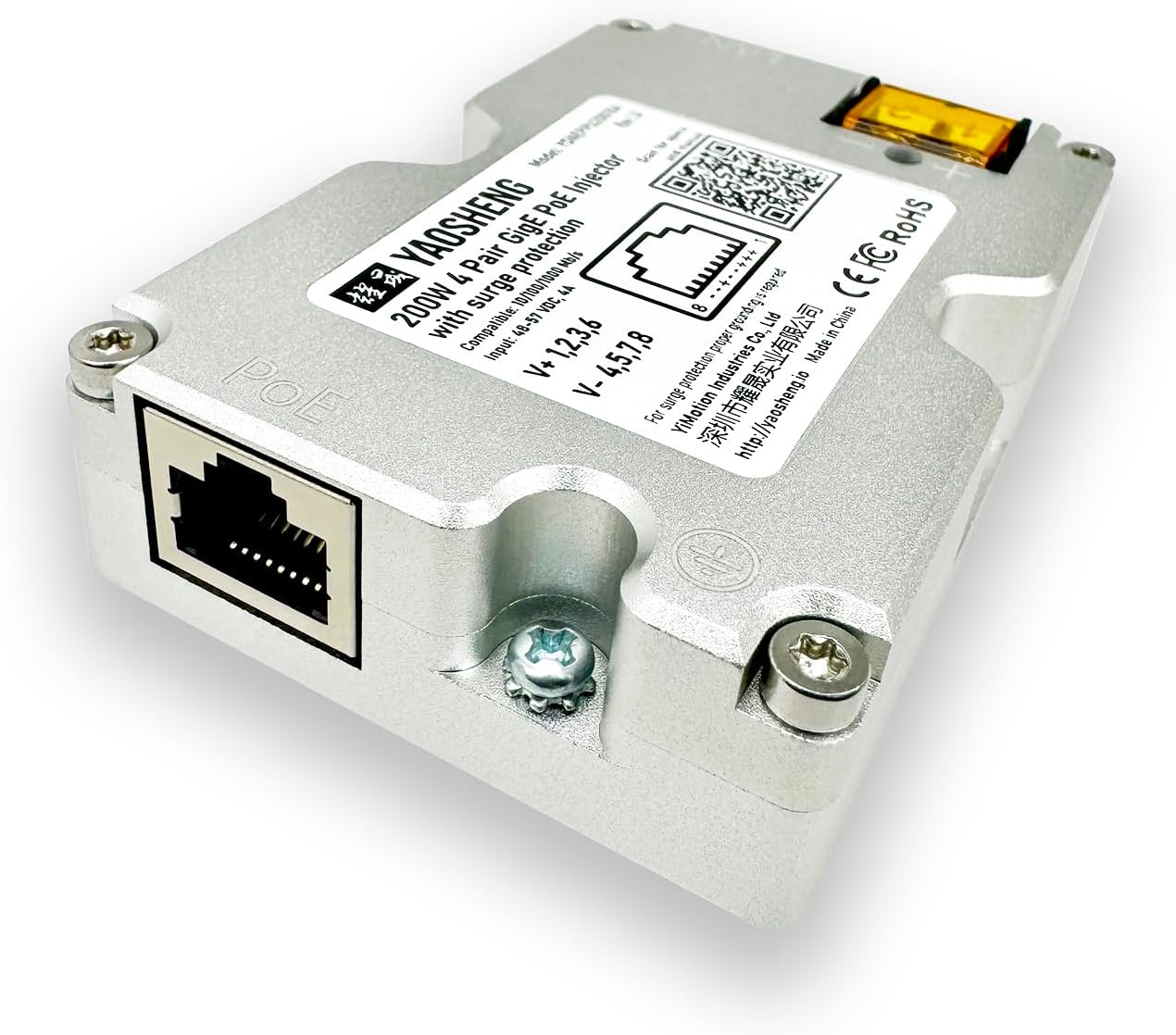
Figure 2: Side view of the YAOSHENG 200W PoE Injector, highlighting the LAN Ethernet port for connection to your network router or switch.

Figure 3: Side view of the YAOSHENG 200W PoE Injector, showing the DC power input terminals with integrated fuse holders for protection.

Figure 4: Top-down view of the YAOSHENG 200W PoE Injector, displaying the product label, QR code for specifications, and connection points. For detailed specifications, scan the QR code or visit yaosheng.io.

Figure 5: Image showing the dimensions of the YAOSHENG 200W PoE Injector, measured with calipers in both millimeters (82mm x 55mm) and inches (3.23in x 2.17in).

Figure 6: Bottom view of the YAOSHENG 200W PoE Injector, showing the mounting points for secure installation.
6. Setup Instructions
Follow these steps to properly install and connect your PoE injector:
- Prepare Cables: Ensure you have a modified Starlink cable (if required for your Starlink model), a standard Ethernet cable, and a 48-57V DC power source.
- Connect Starlink: Connect the modified Starlink cable from your Starlink antenna to the 'PoE' port on the injector. Ensure the shielded connector with T-568B pinout is correctly used.
- Connect Network: Connect a regular Ethernet cable from the 'LAN' port on the injector to your network router or switch.
- Connect Power: Connect your 48-57V DC power source to the DC input terminals (+ and -) on the injector. Observe correct polarity.
- Grounding (Recommended): For enhanced surge protection, connect an optional grounding wire from the designated grounding point on the injector to a reliable earth ground.
- Power On: Once all connections are secure, apply power to the DC input. Observe the LED indicator for operational status.

Figure 7: Diagram illustrating the connection of the PoE Injector between a Starlink antenna (modified cable), a 48V DC power source, and a regular Ethernet cable to a router. Includes details on shielded connectors and optional grounding wire for surge protection.
7. Operating Instructions
The PoE injector operates automatically once connected to power. The LED indicator provides visual feedback on its operational status:
- Green LED: Indicates normal operation. Power is being supplied, and data communication is active.
- Red LED: Indicates a fault condition, such as over-current, short-circuit, or overheating. Disconnect power immediately and troubleshoot.
- Yellow LED: Typically indicates power is applied and the device is initializing or in a standby state.
- Blue/Red Blinking LED: May indicate specific operational states or warnings. Refer to the official product page for detailed interpretations if this state persists.

Figure 8: Green LED indicating normal operation.

Figure 9: Red LED indicating a fault condition.

Figure 10: Yellow LED indicating power on or initialization.

Figure 11: Blue/Red blinking LED indicating specific operational states.
8. Maintenance
To ensure the longevity and optimal performance of your PoE injector:
- Cleaning: Use a soft, dry cloth to clean the exterior of the device. Do not use liquid cleaners or aerosols.
- Fuse Replacement: The device includes integrated fuses. If a fault occurs and the red LED illuminates, check the fuses. Replace blown fuses with ones of the same type and rating (refer to specifications for fuse type). Always disconnect power before replacing fuses.
- Cable Inspection: Periodically inspect all connected cables for damage or wear. Replace any damaged cables immediately.
9. Troubleshooting
If you encounter issues with your PoE injector, refer to the following common problems and solutions:
| Problem | Possible Cause | Solution |
|---|---|---|
| No power/LED off | No power input; faulty power supply; blown fuse. | Check DC power connection; verify power supply output; inspect and replace fuses if necessary. |
| Red LED illuminated | Over-current, short-circuit, or overheating. | Disconnect power. Check for short circuits in cables or connected devices. Ensure adequate ventilation. Allow device to cool if overheated. Reconnect power. |
| No network connectivity | Incorrect cable connection; faulty Ethernet cable; Starlink or router issue. | Verify all Ethernet cables are securely connected to the correct ports. Test cables. Check Starlink and router status independently. |
| Starlink not receiving power | Incorrect DC input voltage; faulty Starlink cable; injector fault. | Ensure DC input is within 48-57V. Check Starlink cable for damage. If other solutions fail, contact support. |
10. Specifications
| Feature | Specification |
|---|---|
| Model Number | YSNEPPU20010A |
| Input Voltage | 48-57 VDC |
| Input Current | 4A (Maximum) |
| Power Output | 200W |
| Data Link Protocol | Gigabit Ethernet |
| Data Transfer Rate | 1000 Megabits Per Second |
| Hardware Interface | Ethernet |
| Compatible Devices | Desktop, Laptop (via network connection), Standard Starlink Models |
| Product Dimensions | 2.2 x 0.81 x 3.3 inches (55 x 20.5 x 84 mm) |
| Item Weight | 3.53 ounces (100 Grams) |
| Protection Features | Input over/under voltage, reverse polarity, over-current, short-circuit, overheating. |
11. Warranty and Support
For warranty information, technical support, or service inquiries, please refer to the official YAOSHENG website or contact your authorized dealer. Keep your purchase receipt for warranty claims.