Introduction
This manual provides detailed instructions for the installation, operation, and maintenance of your ASHATA H511 VD4 Motherboard. Please read this manual thoroughly before proceeding with installation to ensure correct setup and optimal performance. Keep this manual for future reference.
Safety Information
Always observe the following safety precautions:
- Disconnect power from your computer before installing or removing any components.
- Wear an anti-static wrist strap to prevent electrostatic discharge (ESD) damage to components.
- Handle the motherboard by its edges to avoid touching sensitive components.
- Ensure proper ventilation within your PC case to prevent overheating.
- Do not expose the motherboard to moisture or extreme temperatures.
Package Contents
Verify that all items are present in your ASHATA H511 VD4 Motherboard package:
- ASHATA H511 VD4 Motherboard
- I/O Shield
- SATA Data Cables (2x)
- User Manual (this document)
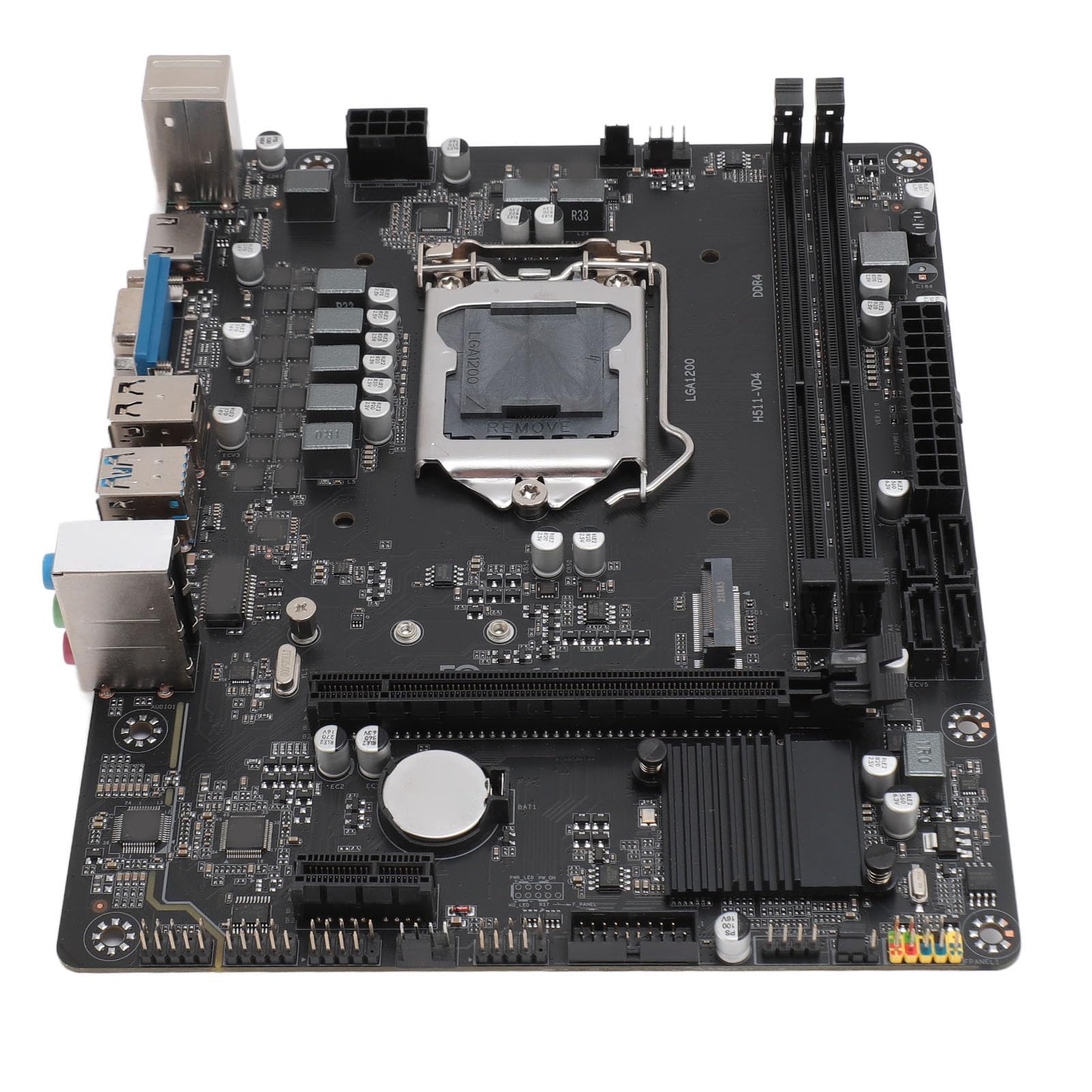
Image: ASHATA H511 VD4 Motherboard, including the I/O shield and two SATA data cables, as typically found in the product package.
Product Overview
The ASHATA H511 VD4 Motherboard is designed for desktop PCs, supporting 10th/11th generation Intel CPUs with an LGA1200 socket. It features dual-channel DDR4 memory slots and multiple expansion interfaces.

Image: Top-down view of the ASHATA H511 VD4 Motherboard, showing the LGA1200 CPU socket, DDR4 memory slots, PCIe slots, and various headers.

Image: Angled view of the ASHATA H511 VD4 Motherboard, highlighting the rear I/O panel with USB ports, video outputs, and audio jacks.
Key Components:
- LGA1200 CPU Socket: Supports 10th and 11th Generation Intel Core processors.
- DDR4 Memory Slots: Dual-channel support for DDR4 SDRAM.
- PCIe x16 Slot: For graphics cards.
- PCIe x1 Slots: For expansion cards.
- M.2 Slot: High-speed storage interface.
- SATA Ports: For connecting storage devices.
- Rear I/O Ports: USB ports, LAN, audio jacks, video outputs (VGA, HDMI if integrated graphics are used).
Setup and Installation
1. Preparing the Case:
Install the I/O shield into the rear opening of your PC case. Ensure it is securely snapped into place.
2. Installing the Motherboard:
- Align the motherboard with the standoffs in your PC case.
- Carefully lower the motherboard onto the standoffs, ensuring the I/O ports align with the I/O shield.
- Secure the motherboard with screws into the standoffs. Do not overtighten.
3. Installing the CPU:
- Open the CPU socket lever.
- Carefully place the CPU into the socket, aligning the golden triangle on the CPU with the triangle on the socket. Do not force it.
- Close the CPU socket lever to secure the CPU.
- Apply thermal paste and install the CPU cooler according to its manufacturer's instructions.
4. Installing Memory (RAM):
- Open the clips on both ends of the DDR4 memory slots.
- Align the notch on the RAM module with the notch in the memory slot.
- Press down firmly on both ends of the RAM module until the clips snap into place.
- For dual-channel performance, install modules in matching slots (refer to motherboard diagram for specific slot pairing).
5. Installing Storage Devices:
- M.2 SSD: Insert the M.2 SSD into the M.2 slot at an angle, then push it down and secure it with the provided screw.
- SATA Drives: Connect SATA data cables from the motherboard's SATA ports to your SSDs/HDDs. Connect power cables from your power supply to the drives.
6. Installing Graphics Card (Optional):
- Open the retention clip on the PCIe x16 slot.
- Align the graphics card with the slot and press down firmly until it clicks into place.
- Secure the card to the case with a screw.
- Connect PCIe power cables from your power supply to the graphics card if required.
7. Connecting Power Supply:
- Connect the 24-pin ATX power connector from your power supply to the motherboard.
- Connect the 8-pin (or 4-pin) CPU power connector to the motherboard.
8. Connecting Front Panel Headers:
Connect the front panel connectors (Power SW, Reset SW, HDD LED, Power LED, USB, Audio) to their respective headers on the motherboard. Refer to the motherboard's silkscreen labels for correct orientation.
Operating Instructions
First Boot:
- After all components are installed and connected, connect your monitor, keyboard, and mouse.
- Turn on the power supply and then press the power button on your PC case.
- The system should boot to the BIOS/UEFI interface or begin the operating system installation process.
BIOS/UEFI Setup:
During boot-up, press the designated key (usually Del or F2) to enter the BIOS/UEFI setup. Here you can configure boot order, system time, fan speeds, and other advanced settings. Save changes before exiting.
Driver Installation:
After installing your operating system, install the necessary drivers for the motherboard chipset, LAN, audio, and any integrated graphics. These drivers are typically available on the manufacturer's website or included on a driver CD/USB (if provided).
Maintenance
- Dust Removal: Regularly clean dust from inside your PC case, especially from fans and heatsinks, using compressed air. Ensure the system is powered off and unplugged before cleaning.
- BIOS/UEFI Updates: Periodically check the ASHATA website for BIOS/UEFI updates. Updates can improve stability, compatibility, and performance. Follow the update instructions carefully to avoid system damage.
- Driver Updates: Keep your system drivers updated to ensure optimal performance and compatibility with new software and hardware.
- Cable Management: Ensure internal cables are neatly managed to improve airflow and prevent interference.
Troubleshooting
- No Power:
- Check if the power supply is switched on and properly connected to the motherboard (24-pin and 8-pin/4-pin CPU power).
- Ensure the front panel power switch cable is correctly connected to the motherboard header.
- Test the power supply with another system or a power supply tester.
- No Display:
- Verify that the monitor is connected to the correct video output (either integrated graphics or dedicated graphics card).
- Reseat the graphics card and RAM modules.
- Try booting with only one RAM stick.
- Check if the CPU power cable is securely connected.
- System Instability/Crashes:
- Check for overheating. Ensure CPU cooler is properly installed and fans are working.
- Run memory diagnostic tools to check for faulty RAM.
- Ensure all drivers are up to date.
- Check for loose cables or connections.
- Peripheral Not Detected:
- Ensure the peripheral is properly connected to the correct port.
- Install the latest drivers for the peripheral.
- Test the peripheral on another port or another computer.
Specifications
| Feature | Specification |
|---|---|
| Brand | ASHATA |
| Model | H511 VD4 |
| CPU Socket | LGA1200 (Supports 10th/11th Gen Intel Core) |
| Memory Technology | DDR4 SDRAM |
| Memory Clock Speed | 2833 MHz (Max) |
| Memory Channels | Dual Channel |
| Graphics Card Interface | Integrated, PCI, PCI-Express x16 |
| Storage Interface | M.2, SATA |
| Power Supply | 6-Phase Power Supply |
| ASIN | B0CS6QDQ35 |
| First Available Date | February 18, 2025 |
Warranty and Support
For warranty information and technical support, please refer to the documentation provided with your purchase or visit the official ASHATA website. Keep your proof of purchase for warranty claims.
Manufacturer: ASHATA
Website: www.ashata.com (Note: This is a placeholder URL. Please refer to your product packaging or official documentation for the correct support website.)