
1. Introduction
The MAYILON MY2600D is a versatile digital clamp meter designed for accurate electrical measurements. It features True-RMS for AC/DC current and voltage, along with capabilities for measuring frequency, capacitance, resistance, temperature, diode, continuity, and Non-Contact Voltage (NCV). This device is suitable for home, automotive, and industrial electrical problem-solving.
Key features include data retention, automatic shut-off, low battery indicator, continuity buzzer, high voltage alert, a backlit LCD screen, and an LED flashlight for use in dimly lit environments.
2. Safety Information
WARNING: To avoid electric shock or personal injury, read all safety information before using this product. Always adhere to local and national safety codes.
- This device complies with IEC 61010-1 safety standard and is rated CAT III 600V.
- Do not apply more than the rated voltage, as marked on the meter, between the terminals or between any terminal and earth ground.
- Use caution when working with voltages above 30V AC RMS, 42V peak, or 60V DC. These voltages pose a shock hazard.
- Before use, inspect the meter, test leads, and accessories for any damage. Do not use if damaged.
- Ensure the function switch is in the correct position for the measurement being performed.
- Do not use the meter if the battery cover is not properly closed.
- When measuring current, ensure the circuit is de-energized before clamping the meter around the conductor.
- Always disconnect the test leads from the circuit before changing functions.
3. What's in the Box
Upon opening your MAYILON MY2600D Digital Clamp Meter package, you should find the following items:
- 1 x Digital Ammeter Pliers (Clamp Meter)
- 2 x Test Pens (Test Leads)
- 1 x Pouch (Carrying Case)
- 1 x User Manual (This document)
- 2 x Battery (AAA batteries, typically)

Image: Unboxing the MAYILON MY2600D Digital Clamp Meter, showing the meter, test leads, carrying pouch, and user manual.
Video: An unboxing and overview of the MAYILON MY2600D Digital Clamp Meter, demonstrating the contents of the package and initial setup.
4. Product Overview
Familiarize yourself with the components of your MAYILON MY2600D Digital Clamp Meter.

Image: Labeled diagram of the MAYILON MY2600D Digital Clamp Meter, highlighting its various parts and controls.
4.1. Controls and Display
- Jaw Assembly: Used for non-contact AC/DC current measurement.
- NCV Sensor Probe: Detects non-contact voltage.
- Function Selector Dial: Rotates to select desired measurement function.
- LCD Display: Shows measurement readings, units, and function indicators. Features a backlight for visibility.
- SEL Button: Selects between different measurement modes within a function (e.g., AC/DC voltage, resistance/diode/continuity).
- REL/Backlight Button: Activates relative measurement mode or turns on/off the display backlight.
- H/Flashlight Button: Holds the current reading on the display or turns on/off the built-in LED flashlight.
- COM Terminal: Common input terminal for test leads (black lead).
- INPUT Terminal: Positive input terminal for test leads (red lead) for voltage, resistance, capacitance, frequency, diode, and temperature measurements.
5. Setup and Battery Installation
5.1. Battery Installation
The MAYILON MY2600D is powered by two AAA batteries. To install or replace batteries:
- Ensure the meter is turned off and disconnect any test leads.
- Locate the battery compartment on the back of the meter.
- Use a screwdriver to open the battery compartment cover.
- Insert two AAA batteries, observing the correct polarity (+ and -) as indicated inside the compartment.
- Replace the battery compartment cover and secure it with the screw.
A low battery indicator will appear on the display when the batteries need replacement.
6. Operating Instructions
Before making any measurements, ensure the test leads are properly connected and the function dial is set to the desired measurement type.
6.1. AC/DC Voltage Measurement
- Insert the red test lead into the "INPUT" terminal and the black test lead into the "COM" terminal.
- Rotate the function dial to the "V~" (AC Voltage) or "V-" (DC Voltage) position. The meter will automatically select AC or DC. If needed, press the "SEL" button to switch between AC and DC voltage.
- Connect the test probes across the circuit or component to be measured.
- Read the voltage value on the LCD display.
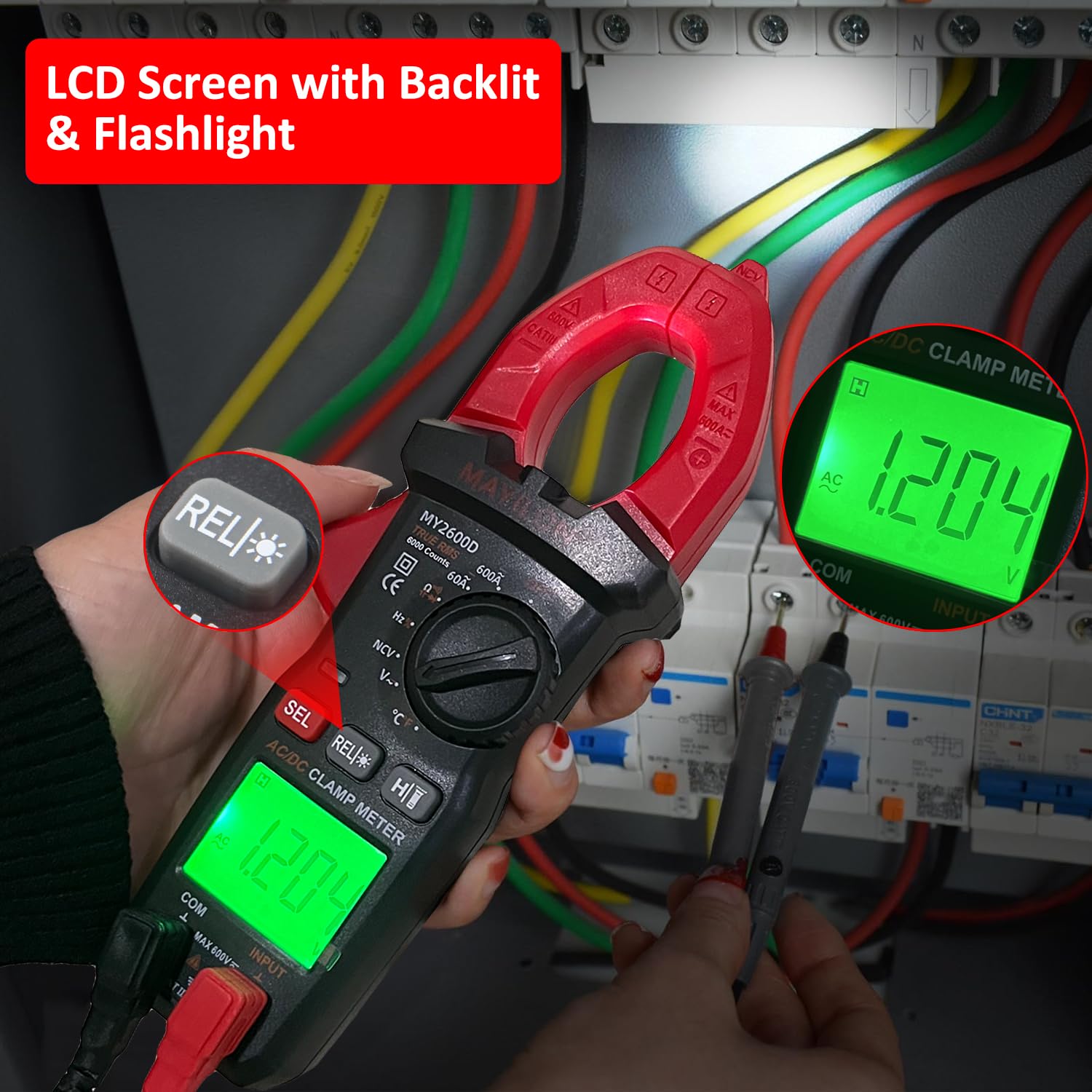
Image: Demonstrating AC/DC Voltage measurement using the test leads connected to a power outlet.
Video: A demonstration of measuring AC voltage from a wall socket and DC voltage from a power supply using the clamp meter's test leads.
6.2. AC/DC Current Measurement (Clamp)
- Rotate the function dial to the "A~" (AC Current) or "A-" (DC Current) position. Press "SEL" to switch between AC and DC current if necessary.
- Open the clamp jaws by pressing the lever.
- Enclose only one conductor of the circuit within the clamp jaws. Ensure the jaws are fully closed.
- Read the current value on the LCD display.

Image: Demonstrating AC/DC Current measurement by clamping the meter around a single wire.
Video: A demonstration of measuring AC current from a power cord and DC current from a motor using the clamp function.
6.3. Resistance Measurement
- Insert the red test lead into the "INPUT" terminal and the black test lead into the "COM" terminal.
- Rotate the function dial to the "Ω" (Resistance) position.
- Connect the test probes across the component to be measured. Ensure the circuit is de-energized.
- Read the resistance value on the LCD display.

Image: Measuring resistance on a circuit board using the test leads.
Video: A demonstration of measuring resistance using the test leads.
6.4. Capacitance Measurement
- Insert the red test lead into the "INPUT" terminal and the black test lead into the "COM" terminal.
- Rotate the function dial to the "Capacitance" symbol position.
- Discharge the capacitor before connecting the test probes. Connect the test probes across the capacitor.
- Read the capacitance value on the LCD display.

Image: Measuring capacitance of a component using the test leads.
Video: A demonstration of measuring capacitance using the test leads.
6.5. Frequency Measurement
To measure frequency, rotate the function dial to the "Hz" position. Connect the test leads across the circuit where frequency needs to be measured. The display will show the frequency in Hertz (Hz).
6.6. Temperature Measurement
- Insert the temperature probe into the "INPUT" and "COM" terminals, observing polarity if applicable.
- Rotate the function dial to the "°C/°F" (Temperature) position.
- Place the tip of the temperature probe on the object or in the environment whose temperature you wish to measure.
- Read the temperature value on the LCD display. Press "SEL" to switch between Celsius and Fahrenheit.

Image: Measuring temperature using the included temperature probe on different surfaces.
6.7. Diode Test
- Insert the red test lead into the "INPUT" terminal and the black test lead into the "COM" terminal.
- Rotate the function dial to the "Diode" symbol position.
- Connect the red probe to the anode and the black probe to the cathode of the diode.
- Read the forward voltage drop on the display. Reverse the probes; the display should show "OL" (Overload) for a good diode.

Image: Performing a diode test using the test leads.
Video: A demonstration of performing a diode test using the test leads.
6.8. Continuity Test
- Insert the red test lead into the "INPUT" terminal and the black test lead into the "COM" terminal.
- Rotate the function dial to the "Continuity" symbol position.
- Connect the test probes across the circuit or component.
- If the resistance is below approximately 50Ω, the buzzer will sound, indicating continuity. The display will show the resistance value.

Image: Performing a continuity test using the test leads.
Video: A demonstration of performing a continuity test using the test leads.
6.9. Non-Contact Voltage (NCV) Detection
- Rotate the function dial to the "NCV" position.
- Place the NCV sensor probe near the conductor or electrical outlet.
- The meter will emit an audible beep and the LED indicator will flash, with the display showing bars, if AC voltage is detected. The intensity of the beeps and the number of bars indicate the strength of the electric field.
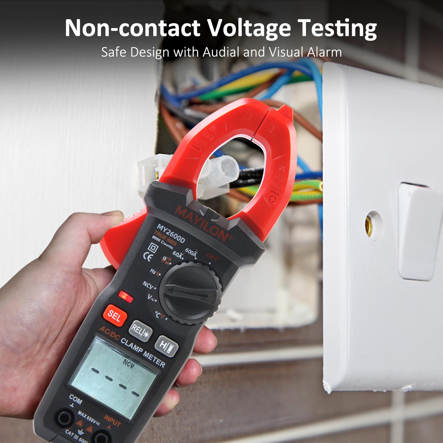
Image: Performing Non-Contact Voltage (NCV) detection near a wall outlet.
6.10. Data Hold and Backlight/Flashlight
- Data Hold (H button): Press the "H" button to freeze the current reading on the display. Press it again to release.
- Backlight (REL/Backlight button): Press and hold the "REL/Backlight" button to turn the LCD backlight on or off.
- Flashlight (H/Flashlight button): Press and hold the "H/Flashlight" button to turn the built-in LED flashlight on or off.

Image: The clamp meter's LCD screen with backlight and the flashlight in use.
7. Maintenance
7.1. Cleaning
Wipe the meter with a damp cloth and mild detergent. Do not use abrasives or solvents. Keep the terminals free of dirt and moisture.
7.2. Battery Replacement
Refer to Section 5.1 for battery installation and replacement instructions. Replace batteries promptly when the low battery indicator appears to ensure accurate readings.
7.3. Storage
If the meter is not used for an extended period, remove the batteries to prevent leakage and damage. Store the meter in a cool, dry place, away from direct sunlight and extreme temperatures.
8. Troubleshooting
| Problem | Possible Cause | Solution |
|---|---|---|
| Meter does not power on. | Dead or incorrectly installed batteries. | Check battery polarity or replace batteries. |
| "OL" (Overload) displayed. | Measurement range exceeded or open circuit. | Select a higher range (if available) or check for an open circuit. |
| Inaccurate readings. | Low battery, incorrect function selected, or poor test lead connection. | Replace batteries, select correct function, ensure secure connections. |
| No continuity beep. | Open circuit or resistance too high. | Check for continuity, ensure resistance is below 50Ω. |
9. Specifications
The following are the general specifications for the MAYILON MY2600D Digital Clamp Meter:
- Brand: MAYILON
- Model Number: MY2600D
- Power Source: Battery Powered (2 x AAA, typically)
- AC/DC Current: Up to 600A
- AC/DC Voltage: Up to 600V
- Resistance: Up to 60MΩ
- Capacitance: Up to 60mF
- Frequency: Up to 9.999MHz
- Temperature: -50°C to 1300°C (-58°F to 2372°F)
- Display: 6000 Counts, Backlit LCD
- Safety Standard: IEC 61010-1, CAT III 600V, CE certified
- Automatic Shut-off: After 15 minutes of inactivity
- Item Weight: 0.43 Kilograms
- Item Dimensions: 19 x 8 x 6 Centimeters

Image: Overview of the MAYILON MY2600D Digital Clamp Meter's measurement capabilities and ranges.
10. Warranty and Support
For warranty information and technical support, please refer to the documentation provided with your purchase or contact MAYILON customer service. Keep your purchase receipt as proof of purchase.