
1. Introduction
This manual provides detailed instructions for the assembly, operation, and maintenance of your Mechanic Master C26 Desktop Portable Mini MATX Case. The C26 is a compact 13.2L chassis designed for Micro-ATX (MATX) and Mini-ITX (ITX) motherboards, offering portability with its integrated handle and support for high-performance components.

Figure 1: Mechanic Master C26 Portable Mini MATX Case (Elegant Black)
The C26 features a 2mm aluminum alloy exterior and a steel internal frame, ensuring durability while maintaining a lightweight profile. Its design prioritizes component compatibility within a small footprint, making it suitable for various build configurations.

Figure 2: Compact Size and Structure Overview. Note: Installation requires careful attention to detail due to the compact design.
2. Setup and Installation
The Mechanic Master C26 case utilizes a double shell structure with multi-faceted detachable panels for ease of access during assembly. Custom countersunk screws are used for secure fastening.

Figure 3: Double Shell Structure and Detachable Panels. Patience is recommended during disassembly and assembly.
2.1 Component Compatibility
- Motherboard: Supports MATX and ITX motherboards.
- Power Supply (PSU): Compatible with SFX power supplies.
- Graphics Card (GPU): Supports GPUs up to 310mm in length and 135mm in width (3-slot).
- CPU Cooler: Accommodates air coolers up to 135mm in height.
- Fans: Supports up to 6 fans (e.g., 2x 8cm/9cm top, 1x 9cm rear, 2x 9cm/12cm bottom).
- Storage: Supports 1x 2.5" SSD.
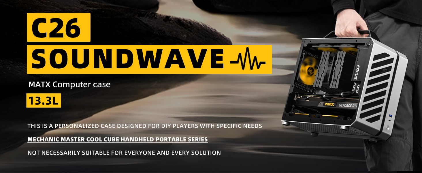
Figure 4: Component Compatibility and Fan Layout. This image details the maximum dimensions for the motherboard, CPU cooler, GPU, and fan placements.
2.2 Assembly Steps
- Disassembly: Carefully remove the side panels and top panel by unscrewing the custom countersunk screws. Keep track of all screws for reassembly.
- Motherboard Installation: Install your MATX or ITX motherboard onto the standoffs. Secure it with the appropriate screws.
- CPU Cooler Installation: Mount your CPU cooler, ensuring it does not exceed the 135mm height limit.
- Power Supply Installation: Install the SFX power supply into its designated bay. Route the power cables as needed.
- GPU Installation: Insert your graphics card into the PCIe slot. Ensure its length (max 310mm) and width (max 135mm) are within limits. Secure it with screws.
- Fan Installation: Install cooling fans in the designated locations (top, rear, bottom) to optimize airflow. Refer to Figure 4 for fan placement.
- Storage Installation: Mount your 2.5" SSD in the available slot.
- Cable Management: Due to the compact nature of the case, careful cable routing is essential to maintain good airflow and aesthetics. Utilize any available tie-down points.
- Front I/O Connections: Connect the front panel cables (USB 3.0, Type-C, power switch) to your motherboard.
- Reassembly: Once all components are installed and cables are managed, reattach the panels using the countersunk screws.

Figure 5: Installation Plan Configuration (MATX + Air Cooler). This diagram illustrates a typical component layout.
2.3 Airflow and Cooling
The C26 case is designed with optimized airflow paths. Air typically flows in from the bottom and out through the top, creating a front-to-back connection for efficient heat dissipation.

Figure 6: Air Cooling Scheme. Red arrows indicate hot air exhaust, blue arrows indicate cool air intake.
3. Operating Instructions
3.1 Powering On/Off
- To power on your system, press the metal power switch located on the front I/O panel.
- To power off, either shut down your operating system normally or press and hold the power switch for several seconds for a forced shutdown.
3.2 Front I/O Ports
The front panel provides convenient access to essential ports:
- USB 3.0 (5G): For high-speed data transfer with compatible devices.
- Type-C (10G): For high-speed data transfer and connectivity with USB-C devices.
- Metal Switch: Power button for system control.

Figure 7: Front I/O Ports and Design Details. Shows the USB 3.0, Type-C, and power switch, along with the aluminum foot pad and handle.
4. Maintenance
4.1 Cleaning the Exterior
- Use a soft, dry cloth to wipe down the aluminum exterior.
- Avoid abrasive cleaners or solvents that may damage the finish.
4.2 Dust Management
- Regularly inspect the case for dust buildup, especially on mesh panels and fan intakes/exhausts.
- Use compressed air to clear dust from fans and internal components.
- For thorough cleaning, the panels can be removed as described in the assembly section.
5. Troubleshooting
If you encounter issues with your system built in the C26 case, consider the following:
- No Power: Ensure all power cables (PSU to wall, PSU to motherboard, CPU, GPU) are securely connected. Verify the power switch on the PSU is in the 'on' position.
- No Display: Check that the monitor cable is connected to the graphics card (not the motherboard integrated graphics, unless no discrete GPU is installed). Reseat the graphics card and RAM modules.
- Overheating: Verify that all case fans and CPU cooler fans are spinning correctly. Ensure proper airflow direction (intake/exhaust). Check for dust buildup obstructing airflow. Confirm CPU cooler is properly seated and thermal paste is applied.
- Component Fit Issues: Double-check component dimensions against the case specifications (GPU length, CPU cooler height). Ensure cables are not obstructing component installation or panel closure.
- Loose Connections: Re-verify all internal connections, including power, data, and front panel headers.
6. Specifications
The following table details the technical specifications of the Mechanic Master C26 case:
| Feature | Specification |
|---|---|
| Product Name | C26 Soundwave |
| Dimensions (L×W×H, excluding foot pad) | 315mm × 158mm × 266mm (12.4 x 6.2 x 10.5 inches) |
| Material (Outer Frame) | 2mm Aluminum Alloy |
| Material (Inner Frame) | 1mm SPCC Steel |
| Motherboard Support | ITX, MATX |
| CPU Cooler Support | 135mm Tower Cooler (Max Height) |
| GPU Support | Up to 310mm Length |
| Power Supply Support | SFX |
| Front I/O | Metal Switch, Type-C (10G), USB 3.0 (5G) |
| Gross Weight | 3.0 Kg (6.6 pounds) |
| Net Weight | 3.0 Kg |
| Optional Configuration | Ventilation aluminum side panel |

Figure 8: C26 Soundwave Product Specifications.
7. Warranty and Support
For warranty information and technical support, please refer to the documentation provided with your purchase or contact Mechanic Master customer service directly. Keep your proof of purchase for any warranty claims.