1. Introduction
This manual provides comprehensive instructions for the installation, operation, and maintenance of your CO-Z Infrared Sensor Set, Model AGO-WH00-0Z. This sensor set is designed to enhance safety for gate openers by detecting obstacles such as vehicles and pedestrians, automatically halting gate movement. It features a rotatable lens for flexible installation and can be used in various outdoor applications.
2. Product Components
The CO-Z Infrared Sensor Set consists of two main units: an Emitter and a Receiver. The Emitter sends an infrared beam, and the Receiver detects it. An interruption of this beam triggers the safety mechanism.

Figure 2.1: Internal view of the Receiver and Emitter units. The Receiver includes a Buzzer Switch, Photocell Switch, Power Input, Low Battery Alarm Output, and Photocell. The Emitter includes a Safety Switch, Power Input, and can be powered by batteries or 12-24V AC/DC.
3. Setup and Installation
Proper installation is crucial for the optimal performance and safety of your infrared sensor set. Follow these steps carefully.
3.1 Mounting Location
Select a location where the emitter and receiver can be mounted directly opposite each other, ensuring an unobstructed line of sight for the infrared beam. The sensor range is between 6'7" and 39'5". Consider installing the sensors at a suitable low height for optimal detection of both adult and child pedestrians.
3.2 Mounting Options
The sensor lens can rotate 180 degrees, allowing for flexible installation. You can choose between face mounting or side mounting depending on your gate structure and desired beam path.

Figure 3.1: Illustration of 0-180° rotatable lens for face mounting and side mounting configurations.
3.3 Powering the Sensors
- Receiver: The receiver unit requires a 12–24V AC/DC power supply.
- Emitter: The emitter unit can be powered by two AA batteries (not included) or by a 12–24V AC/DC power supply. Using batteries for the emitter can simplify installation by reducing wiring requirements.
Ensure all power connections are secure and correctly wired according to the polarity indicated on the units.
3.4 Alignment
After mounting, ensure the emitter and receiver are perfectly aligned so the infrared beam can travel unobstructed between them. A misalignment can prevent the system from functioning correctly. Some units may have indicator lights to assist with alignment.
4. Operating Instructions
Once installed and powered, the CO-Z Infrared Sensor Set operates automatically to provide safety for your gate opener.
4.1 Automatic Obstacle Detection
The sensors continuously transmit and receive a 940 nm, 1.9 kHz IR beam signal. If an obstacle (such as a vehicle or pedestrian) breaks this beam, the sensors detect the interruption within 50 milliseconds. This rapid detection ensures that your gate opener receives an immediate signal to halt its movement, preventing potential accidents.
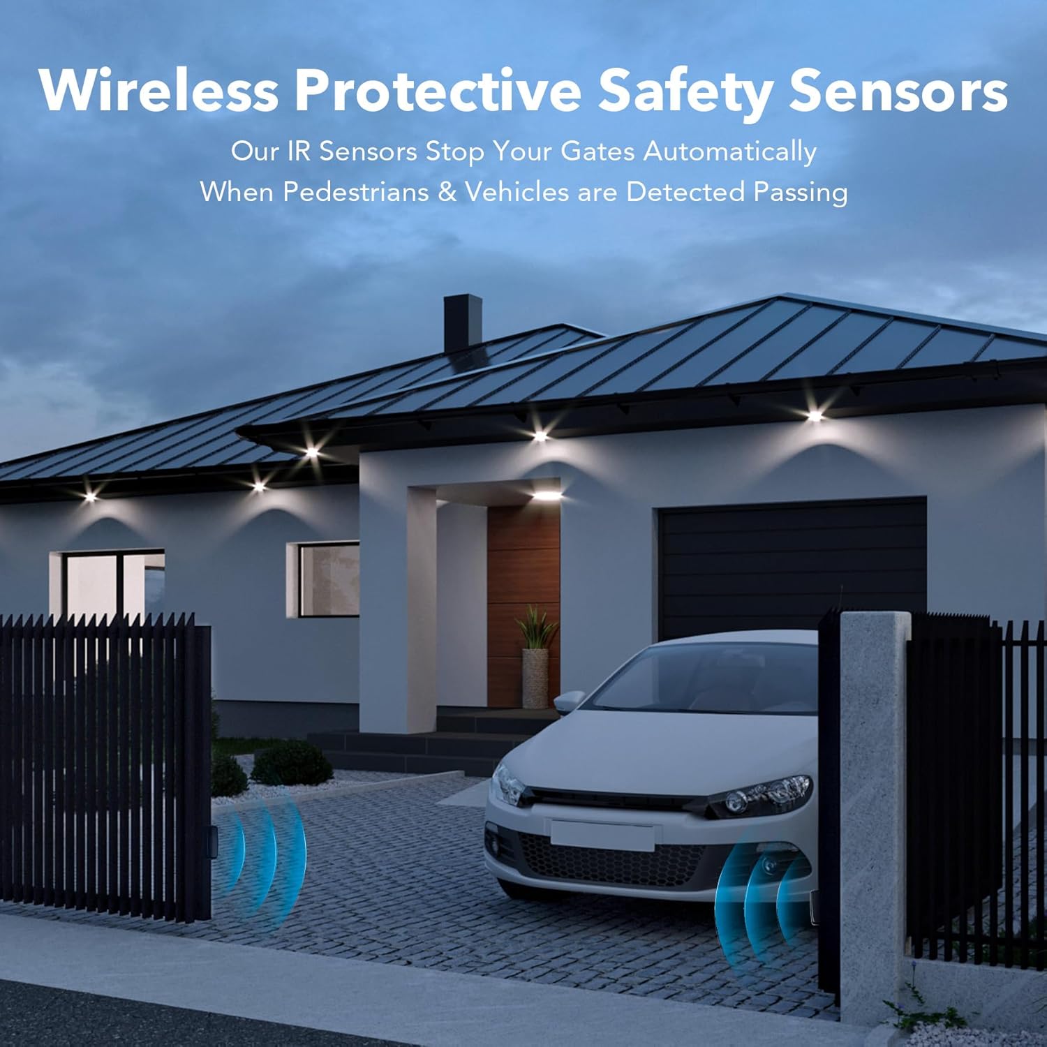
Figure 4.1: Wireless protective safety sensors detecting a vehicle at a gate.
4.2 Tracking Angle and Sensitivity
The sensors feature a 5° tracking angle, contributing to their ultra-sensitive detection capabilities. This allows for precise monitoring of the gate's path.

Figure 4.2: Key technical specifications highlighting the sensor's sensitivity and range.
5. Maintenance
Regular maintenance ensures the longevity and reliable operation of your CO-Z Infrared Sensor Set.
5.1 Cleaning
Periodically clean the lenses of both the emitter and receiver units. Dust, dirt, spiderwebs, or other debris can obstruct the infrared beam and impair sensor performance. Use a soft, damp cloth to gently wipe the lenses. Avoid abrasive cleaners.
5.2 Battery Replacement (Emitter)
If your emitter unit is powered by AA batteries, monitor for low battery indicators (if available) or replace batteries periodically to ensure continuous operation. The frequency of replacement will depend on usage and battery type.
5.3 Weather Protection
The sensors are designed with IP55 weatherproofing, offering protection against dust and water splashes. While robust, extreme weather conditions may temporarily affect performance. Ensure the units are securely mounted to withstand wind and other environmental factors.
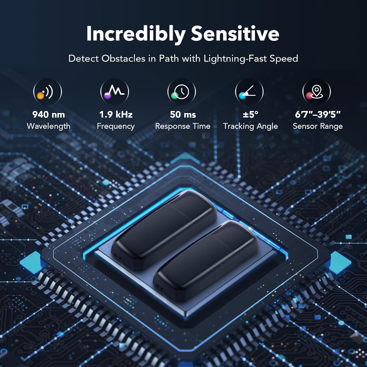
Figure 5.1: All-weather protection features of the sensor.
6. Troubleshooting
If you encounter issues with your infrared sensor set, consider the following common troubleshooting steps:
- No Detection / False Alarms:
- Check alignment: Ensure the emitter and receiver are perfectly aligned and facing each other.
- Clear obstructions: Remove any physical obstructions (e.g., leaves, spiderwebs, dirt) from the path of the infrared beam and the sensor lenses.
- Verify power: Confirm both units are receiving adequate power. For battery-powered emitters, check battery levels and replace if necessary.
- Environmental factors: Heavy fog, rain, or direct sunlight can sometimes interfere with infrared beams. Wait for conditions to improve or adjust sensor positioning if possible.
- Gate Not Stopping:
- Check wiring: Ensure the sensor's output is correctly wired to your gate opener's safety input.
- Test sensor functionality: Manually break the beam to see if the sensor registers an interruption (e.g., if an indicator light changes or a buzzer sounds).
If problems persist after performing these checks, contact customer support for further assistance.
7. Specifications
| Feature | Specification |
|---|---|
| Brand | CO-Z |
| Model Number | AGO-WH00-0Z |
| Color | Black |
| Power Source (Emitter) | Battery Powered (2x AA, not included) or 12–24V AC/DC |
| Power Source (Receiver) | 12–24V AC/DC |
| Maximum Range | 39 Feet (approx. 12 meters) |
| Minimum Range | 6'7" (approx. 2 meters) |
| Mounting Type | Wall Mount |
| Lens Rotation | 0-180° |
| Wavelength | 940 nm |
| Frequency | 1.9 kHz |
| Response Time | 50 ms |
| Tracking Angle | ±5° |
| Weatherproofing | IP55 |
| Compatible Devices | Security Systems, Gate Openers |
| Item Weight | 5.6 ounces (approx. 159 grams) |
| Package Dimensions | 5.79 x 4.29 x 1.54 inches |
8. Warranty Information
Specific warranty details for the CO-Z Infrared Sensor Set (Model AGO-WH00-0Z) may vary. Please refer to the product packaging, the seller's website, or contact CO-Z customer service directly for the most accurate and up-to-date warranty information.
9. Customer Support
For technical assistance, questions regarding installation, operation, or troubleshooting beyond the scope of this manual, please contact CO-Z customer support. Refer to your purchase documentation or the official CO-Z website for contact details.


