1. Introduction
This manual provides detailed instructions for the installation, operation, and maintenance of your UMLIFE REX-C100 PID Temperature Controller Kit. This kit is designed for precise temperature control in various industrial and scientific applications, including light industry, chemistry, machinery, metallurgy, ceramics, petrification, food & beverage, smokers, incubators, ovens, furnaces, and plastic extruder heating processes. Please read this manual thoroughly before use to ensure safe and efficient operation.
2. Package Contents
Verify that all components listed below are included in your package:
- 1 x REX-C100 PID Temperature Controller
- 1 x K-Type Probe Sensor (Thermocouple)
- 1 x SSR-25DA Solid State Relay
- 1 x White Heat Sink
3. Product Overview
The UMLIFE REX-C100 PID Temperature Controller Kit consists of several key components working together to provide accurate temperature regulation.
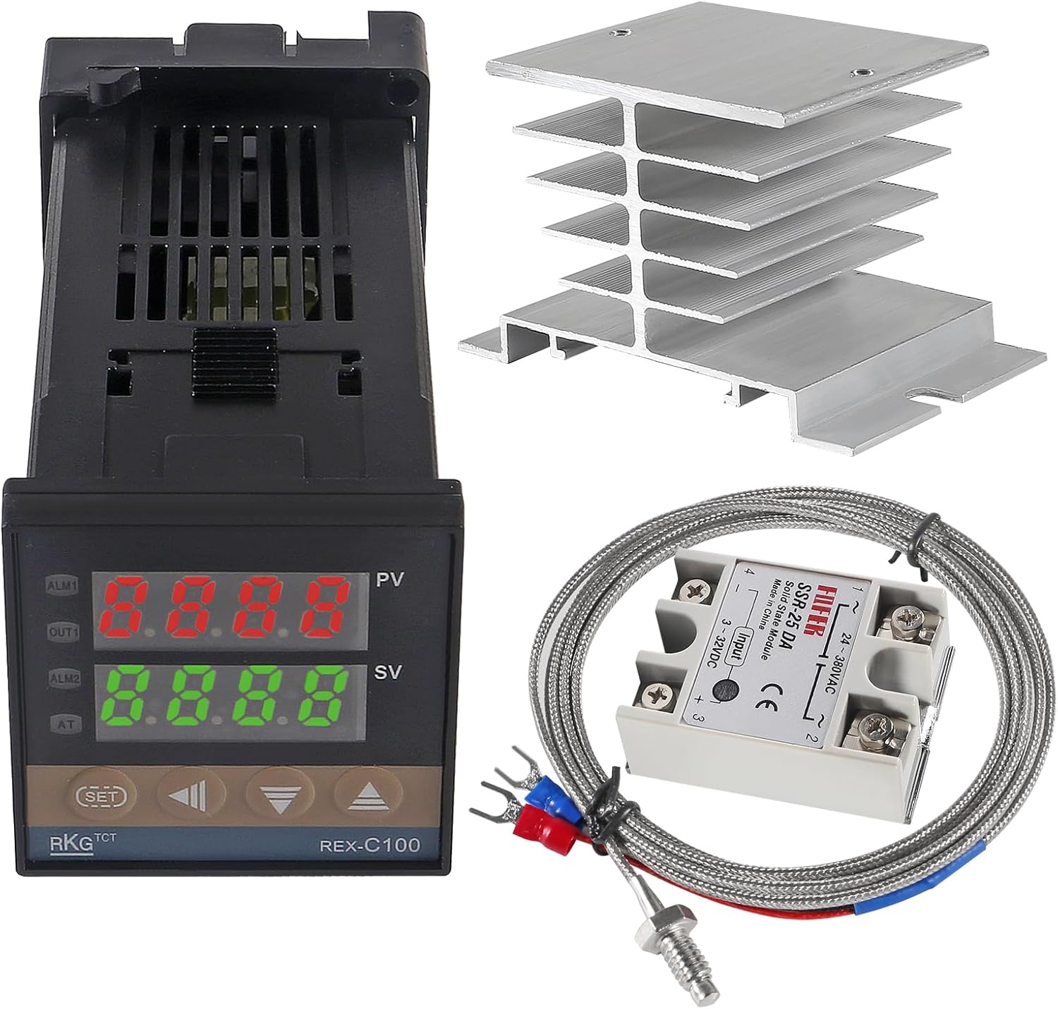
Figure 3.1: Complete UMLIFE REX-C100 PID Temperature Controller Kit showing the controller, SSR, K-type thermocouple, and heat sink.
3.1 REX-C100 PID Temperature Controller
This is the main control unit, featuring an industrial-grade professional self-tuning PID technology for rapid temperature control, fast response, minimal overshoot, and high precision. It displays both the process value (PV) and set value (SV).

Figure 3.2: REX-C100 PID Temperature Controller with approximate dimensions of 48.5mm x 48.5mm x 107mm (1.90in x 1.90in x 4.21in).
3.2 SSR-25DA Solid State Relay
The Solid State Relay (SSR) acts as an electronic switch, controlled by the PID controller, to manage the power supplied to the heating element. The SSR-25DA model has an input voltage range of 3-32V DC and a load voltage range of 24-380V AC, with a maximum load current of 25 Amp.

Figure 3.3: SSR-25DA Solid State Relay with approximate dimensions of 45mm x 62.5mm x 24mm (1.77in x 2.46in x 0.94in).
3.3 K-Type Thermocouple Thread Probe
This sensor measures the temperature. It is a K-type thermocouple with a measuring range of 32~1112°F (0~600°C). The probe features a threaded design for secure installation.

Figure 3.4: K-Type Thermocouple Thread Probe with a sensor diameter of 4.5mm (0.18in) and a cable length of 2 meters (6.6ft).
3.4 White Heat Sink
The heat sink is essential for dissipating heat generated by the Solid State Relay, ensuring its longevity and stable operation. It is made of aluminum.

Figure 3.5: White Heat Sink with approximate dimensions of 80mm x 59mm x 49mm (3.14in x 2.32in x 1.92in).
4. Specifications
| Component | Specification |
|---|---|
| REX-C100 PID Controller | |
| Measuring Accuracy | ±0.5%FS |
| Cold-end Compensation Tolerance | ±2℃ (can be modified by software in 0~50℃) |
| Resolution | 14 bit |
| Sampling Cycle | 0.5 Sec |
| Power Supply | AC 100V-240V 50/60HZ |
| Relay Output | Contact capacity 250V AC 3A (resistive load) |
| Alarm Function Output | 2 ways |
| Proportional Band (P) | 0~full range (ON/OFF control when set to 0) |
| Detecting Temperature Range | 0℃~1300℃ (for Controller) |
| Insulation Resistance | >50M ohm (500V DC) |
| Dielectric Strength | 1500V AC/min |
| Power Consumption | <10 VA |
| Service Environment | 0℃~50℃ |
| Dimensions | Approx. 48x48x110mm |
| SSR-25DA Solid State Relay | |
| Input Voltage | 3-32V DC |
| Load Voltage | 24-380V AC |
| Max Load Current | 25 Amp |
| K-Type Thermocouple | |
| Type | K Type |
| Measuring Range | 32~1112°F (0~600°C) |
| Cable Length | 2M / 6.6ft |
| Heat Sink | |
| Material | Aluminum |
| Screw Thread | M4 |
| Dimensions (Roof) | 50mm x 60mm |
| Dimensions (Foot) | 80mm x 50mm |
| Height | 50mm |
5. Setup and Wiring
Proper wiring is crucial for the safe and correct operation of the PID temperature controller kit. Always ensure power is disconnected before performing any wiring.
5.1 General Wiring Guidelines
- Power Supply: The REX-C100 controller is designed for AC 100V-240V 50/60HZ. Ensure your power source matches this requirement.
- Thermocouple Connection: Connect the K-type thermocouple to the designated input terminals on the REX-C100 controller. The red fork typically connects to the positive (+) pole, and the blue fork to the negative (-) pole. Refer to the wiring diagram on the controller itself for exact pin assignments.
- SSR Connection: The REX-C100 controller's output (usually labeled 'OUT') connects to the input terminals of the SSR-25DA (3-32V DC side). The load (heating element) connects to the output terminals of the SSR (24-380V AC side).
- Heat Sink Installation: Mount the SSR-25DA onto the provided heat sink using M4 screws. It is highly recommended to apply thermal paste between the SSR and the heat sink to ensure efficient heat transfer.
- Load Connection: Connect your heating element or other load to the output terminals of the SSR. Ensure the load's voltage and current requirements are within the SSR's specifications (24-380V AC, max 25 Amp).
5.2 Voltage Compatibility Note
Important: While the product description states 100V-240V AC, some users have reported issues with 120V operation, suggesting it may function optimally or exclusively on 220V AC. Always verify the specific voltage requirements printed on your unit and consult a qualified electrician if you are unsure about your power supply or wiring. Incorrect voltage can damage the device and pose a safety risk.
6. Operating Instructions
Once properly wired and powered on, the REX-C100 controller will display the current process value (PV) and the set value (SV).
6.1 Setting the Temperature (SV)
- Press the SET button once. The SV display will begin to flash.
- Use the Up (▲) and Down (▼) arrow buttons to adjust the desired temperature.
- Press the SET button again to confirm the new set value. The display will stop flashing, and the controller will begin to regulate the temperature to the new SV.
6.2 Advanced Settings (PID Parameters)
The REX-C100 features self-tuning PID capabilities. For most applications, the default or auto-tuned settings are sufficient. To access advanced parameters (such as P, I, D values, alarm settings, etc.), typically you would press and hold the SET button for several seconds until the parameter codes appear. Refer to the detailed wiring diagram or a more comprehensive REX-C100 manual for specific parameter definitions and adjustment procedures.
7. Maintenance
To ensure optimal performance and longevity of your temperature controller kit, follow these maintenance guidelines:
- Cleaning: Keep the controller and components clean and free from dust and debris. Use a soft, dry cloth for cleaning. Do not use abrasive cleaners or solvents.
- Connections: Periodically check all electrical connections to ensure they are secure and free from corrosion. Loose connections can lead to erratic behavior or component failure.
- Heat Sink: Ensure the heat sink remains clear of obstructions to allow for proper airflow and heat dissipation. Overheating of the SSR can lead to premature failure.
- Environmental Conditions: Operate the unit within its specified service environment (0℃~50℃) and avoid excessive humidity or corrosive atmospheres.
8. Troubleshooting
If you encounter issues with your UMLIFE PID Temperature Controller Kit, refer to the following common problems and solutions:
| Problem | Possible Cause | Solution |
|---|---|---|
| Controller display flickers or does not power on. | Incorrect power supply voltage (e.g., 120V instead of 220V if unit is 220V only), loose power connection. | Verify power supply voltage matches unit requirements. Check all power connections. Consult a qualified electrician. |
| Temperature reading is inaccurate or shows 'HHHH' / 'LLLL'. | Thermocouple not connected correctly, damaged thermocouple, incorrect thermocouple type selected in settings. | Check thermocouple wiring (red to +, blue to -). Inspect thermocouple for damage. Ensure K-type is selected in controller settings. |
| Heating element does not turn on/off. | SSR wiring incorrect, SSR faulty, controller output faulty, heating element faulty. | Verify SSR input/output wiring. Test SSR functionality. Check controller output signal. Test heating element continuity. |
| Temperature overshoots or oscillates. | PID parameters not optimized for the system. | Initiate the auto-tuning function on the REX-C100 (refer to specific REX-C100 manual for auto-tune procedure). Manually adjust PID parameters if auto-tuning is insufficient. |
| SSR gets excessively hot. | Inadequate heat sinking, no thermal paste, overloaded SSR. | Ensure heat sink is properly installed with thermal paste. Verify load current does not exceed SSR's maximum rating (25 Amp). Ensure proper ventilation around the heat sink. |
9. Safety Information
WARNING: This product involves high voltage electricity. Improper installation or use can result in electric shock, fire, or serious injury. Always follow these safety precautions:
- Always disconnect power before installing, wiring, or performing maintenance on the unit.
- Ensure all wiring is done by a qualified individual and complies with local electrical codes.
- Do not operate the unit with damaged components or wiring.
- Ensure proper grounding for all electrical components.
- Keep the unit away from water, moisture, and flammable materials.
- Do not exceed the specified voltage and current ratings for any component.
- Install the unit in a well-ventilated area to prevent overheating.
10. Warranty and Support
UMLIFE products are manufactured to high-quality standards. For specific warranty details, please refer to the product packaging or contact your retailer. If you require technical assistance or have questions regarding the operation of your PID Temperature Controller Kit, please contact UMLIFE customer support through the retailer's platform or the official UMLIFE website.
Please have your product model number (REX-C100) and purchase information ready when contacting support.