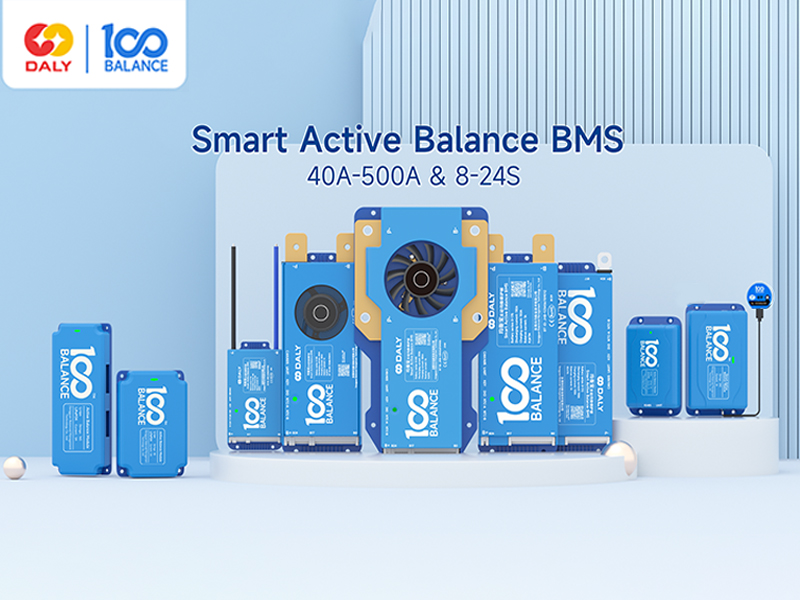
1. Introduction
This manual provides detailed instructions for the 100BALANCE Smart Active Balance Battery Management System (BMS), Model 40A 4S-8S. This intelligent BMS is designed to protect and manage Li-ion, LiFePO4, and LTO lithium battery packs, ensuring their safety and extending their lifespan. Key features include continuous 1A active balancing current, comprehensive protection functions, and smart monitoring via Bluetooth and PC software.
2. Safety Information
Always prioritize safety when working with battery systems. Incorrect installation or handling can lead to serious injury or damage to the battery pack and BMS. Please read and understand all instructions before proceeding.
- Overcharge Protection: Prevents battery cells from being charged beyond their safe voltage limit.
- Over-discharge Protection: Safeguards cells from discharging below their minimum safe voltage.
- Overcurrent Protection: Protects against excessive current during charge and discharge cycles.
- Short Circuit Protection: Automatically disconnects the battery in case of a short circuit.
- Temperature Protection: Monitors and protects the battery from extreme temperatures.
- Pre-charge Protection: Manages initial charging to prevent current surges.
- Misconnection Protection: Designed to prevent damage from incorrect wiring (limited to 6 strings).
- Parallel Connection Current Limiting: Ensures safe operation when multiple battery packs are connected in parallel.
- Cell Balancing: Actively balances cell voltages to optimize battery performance and longevity.
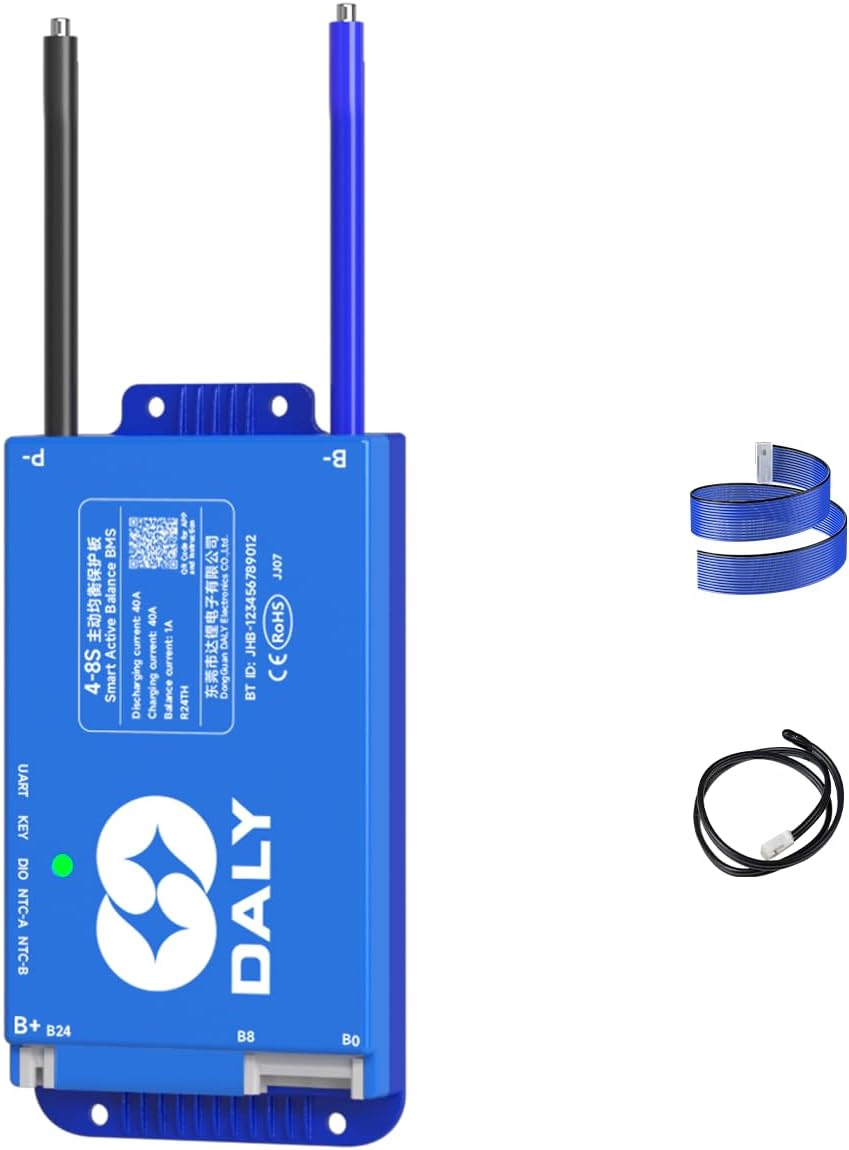
3. Package Contents
Verify that all items are present in the package:
- Smart Active Balance BMS (1 unit)
- Sampling Cable (1 unit)
- P-&B- Cable (1 unit)
- B+ Cable (1 unit)
- NTC Temperature Sensor (1 unit)
- Screws (2 units)
- Operation Manual (1 unit)

4. Setup and Installation
Proper wiring is crucial for the safe and correct operation of the BMS. Follow these steps carefully.
4.1. Battery Pack Preparation
Ensure your battery pack is assembled correctly with all cells connected in series. Identify the total positive (B+) and total negative (B-) terminals of the battery pack.
4.2. Sampling Cable Wiring
- Connect the black wire of the sampling cable to the total negative (B-) terminal of the battery pack.
- Connect the first red wire of the sampling cable to the positive terminal of the first cell (B1+). Continue connecting each subsequent wire to the positive terminal of each cell in sequence (B2+, B3+, etc.).
- Ensure the wiring sequence is strictly followed. Reversing the wiring sequence can damage the BMS.
- If using a BMS with more sampling wires than your battery pack requires (e.g., an 8-17S BMS for an 8S pack), seal the unused wires with insulation tape to prevent short circuits.

4.3. NTC Temperature Sensor Connection
Plug the NTC cable into the NTC-A port on the BMS. Position the NTC sensor to accurately monitor the battery pack's temperature.
4.4. Main Power Cable Connection
- Connect the B- cable from the BMS to the total negative (B-) terminal of the battery pack.
- Connect the P- cable from the BMS to the negative terminal of your load/charger.
- Connect the B+ cable from the BMS to the total positive (B+) terminal of the battery pack.
4.5. Pre-Installation Voltage Check
Before plugging the sampling cable into the BMS, use a multimeter to measure the voltage across each pair of adjacent wires on the sampling cable connector. Ensure the voltage readings are consistent and correct for your battery cell type. This step helps prevent damage from miswiring.
4.6. Final Connection
Once all individual wires are correctly connected and verified, carefully plug the sampling cable connector into the corresponding port on the BMS.
5. Operating Instructions
5.1. Bluetooth App Monitoring
The 100BALANCE BMS features built-in Bluetooth connectivity, allowing you to monitor and control your battery pack via a mobile application (Android or iOS).
- Download the 'Balance BMS' app from your device's app store.
- Open the app and select 'Local monitoring' to connect via Bluetooth.
- The app displays real-time battery status, including total voltage, current, State of Charge (SOC), cell voltages, temperatures, and alarm information.
- You can adjust various settings and control charge/discharge functions directly from the app.

5.2. PC Host Software
For advanced monitoring, parameter setting, and firmware upgrades, use the 100BALANCE PC Host software.
- Download: Obtain the PC Host software from the official 100BALANCE website (Service > Download > Application program download) or contact customer service for a direct link.
- Connection: Connect the BMS to your PC using a UART cable. Ensure the correct COM port and baud rate (9600 for UART, 250 for CAN) are selected in the software.
- Live Data: View real-time battery data, including total voltage, current, SOC, cell voltages, MOS temperature, and environmental status.
- Set Parameters: Access the 'Set Param' page to configure balance current, sleep time, rated capacity, and various protection parameters. Enter the default password (20211115) to enter management mode.
- Engineering: Calibrate current readings for accuracy and configure BMS accessories like fan start/stop temperatures, key switch functions, and buzzer settings.
- BMS Upgrade: Use the 'BMS Upgrade' section to load and install new firmware versions.
5.3. Communication and Accessories
The BMS supports various communication methods and accessories for enhanced functionality:
- UART Cable: For PC host connection.
- RS485 Cable: For communication with other devices.
- CAN BUS: For industrial communication protocols.
- WiFi Module: Enables remote monitoring and control via IoT cloud.
- LCD Displays (3.0 inch, 4.3 inch Touch Display): Provide real-time battery information and allow parameter changes directly on the screen.
- Heating Module: Used in cold environments to pre-heat the battery pack, ensuring optimal performance.
- Key Switch Button: Can be used to switch the discharge MOSFET on/off.
- Inverter Connection Line: Allows direct connection to compatible inverters.

6. Maintenance
Regular maintenance ensures the longevity and optimal performance of your battery pack and BMS.
- Visual Inspection: Periodically check all wiring connections for looseness, corrosion, or damage.
- Parameter Monitoring: Regularly monitor battery parameters via the mobile app or PC Host software to detect any anomalies.
- Cell Balancing: The 1A active balancing function continuously works to equalize cell voltages. Ensure this function is enabled in the settings.
- Firmware Updates: Keep the BMS firmware updated to the latest version for improved performance and new features.
7. Troubleshooting
If you encounter issues with your BMS, refer to the following guidelines:
- Alarm List: Check the 'Alarm List' in the mobile app or 'His Data' section of the PC Host software for any recorded fault codes or warnings.
- Wiring Issues: Incorrect wiring is a common cause of problems. Double-check all connections, especially the sampling wires, for correct sequence and secure contact.
- Communication Problems: If the app or PC software cannot connect, verify Bluetooth is enabled, the UART cable is properly connected, and the correct COM port/baud rate are selected.
- Parallel Connection: When paralleling lithium battery packs, ensure the discharging MOS is manually disconnected in the Bluetooth app or PC software to prevent high current triggering short circuit protection. The voltage difference between parallel packs should be less than 1 volt.
- SOC Calibration: If the State of Charge (SOC) reading is inaccurate, perform an SOC 100% calibration. This is typically triggered when single cell overvoltage protection level 2 is reached, calibrating the BMS to 100% SOC.
8. Specifications
Detailed technical specifications for the 100BALANCE Smart Active Balance BMS (Model 40A 4S-8S).
| Feature | Specification |
|---|---|
| Model Number | 40A 4S-8S |
| Package Dimensions | 8.79 x 5 x 2.36 inches |
| Item Weight | 12.3 ounces (0.35 Kilograms) |
| Cell Sampling Voltage Range | 1.5V-4.9V |
| Operating Voltage Range | >10V |
| Active Balance Current | 1A |
| Working Power Consumption | 1.25W |
| Sleep Current | <0.025mA |
| Working Temperature | -40°C-85°C |
| Temperature Detection Quantity | 4 |
| Temperature Protection | Yes |
| Short Circuit Protection | Yes |
| Coulomb Counter | Yes |
| Indicator Light | Green: works properly; Red: alarm or protection |
| Support Communication Port | UART |
| Customizable Communication Port | CAN/485 |
9. Warranty and Support
The 100BALANCE Smart Active Balance BMS comes with a 3-year warranty.
For technical assistance, troubleshooting, or warranty claims, please contact 100BALANCE customer service. Provide your product model number and a detailed description of the issue for efficient support.