
1. Introduction
The Daconovo 616 is a compact, auto-ranging, true RMS digital multimeter designed for accurate and reliable electrical measurements. It features a 6000-count LCD display, non-contact voltage (NCV) detection, and a built-in flashlight, making it suitable for various electrical testing applications.
This manual provides essential information for the safe and effective use of your Daconovo 616 multimeter. Please read it thoroughly before operation and keep it for future reference.
2. Safety Information
WARNING: To avoid electric shock or personal injury, read and understand all safety information before using this product.
- Always ensure the test leads are in good condition and properly connected.
- Do not measure voltages exceeding the specified maximum input limits (600V AC/DC).
- Exercise extreme caution when working with live circuits.
- Do not use the multimeter if it appears damaged or is not operating correctly.
- Replace batteries promptly when the low battery indicator appears.
- Always disconnect test leads from the circuit before changing functions.
3. Product Overview
The Daconovo 616 Smart Digital Multimeter is a versatile tool for electrical diagnostics. Its compact design and comprehensive features make it ideal for both professionals and DIY enthusiasts.
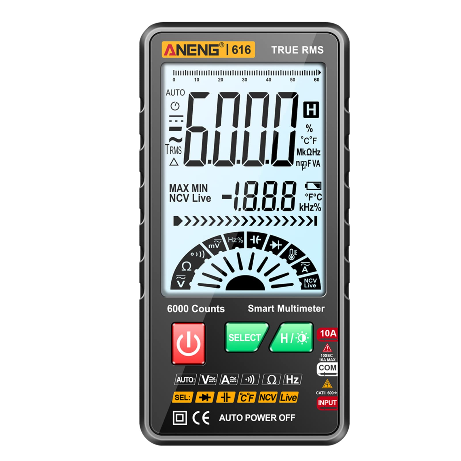
Figure 3.1: Front view of the Daconovo 616 Multimeter, highlighting its large display and function buttons.
Key Features:
- Smart Multimeter with Multiple Functions: Measures AC/DC current, AC/DC voltage, resistance, capacitance, temperature, frequency, continuity, diode, and firewire detection.
- Non-Contact Voltage (NCV) Detection: Safely detects AC voltage without direct contact.
- Flashlight Function: Provides auxiliary lighting for working in dark or low-light environments.
- Large LCD Display: 3.5-inch screen for clear and convenient data viewing.
- Compact and Accurate: Portable design with a high-performance chip for precision measurements.
- Additional Functions: Data hold, auto power-off, Celsius/Fahrenheit temperature units, True RMS.

Figure 3.2: The Daconovo 616 Multimeter packaged with its test leads, thermocouple, and zippered pouch.
4. Setup
4.1 Battery Installation
- Ensure the multimeter is powered off.
- Locate the battery compartment cover on the back of the device.
- Use a screwdriver to open the battery compartment.
- Insert two 1.5V AAA batteries, observing the correct polarity (+/-).
- Replace the battery compartment cover and secure it with the screw.
4.2 Connecting Test Leads
For most measurements, connect the red test lead to the 'VΩHz' input jack and the black test lead to the 'COM' input jack. For current measurements (up to 10A), connect the red test lead to the '10A' input jack and the black test lead to the 'COM' input jack.

Figure 4.1: Multimeter with test leads connected, demonstrating a resistance measurement setup.
5. Operating Modes
Press the POWER button to turn the multimeter on or off. Use the SELECT button to cycle through different measurement modes within a function group (e.g., AC Voltage / DC Voltage).
5.1 Voltage Measurement (AC/DC)
Connect the red test lead to the 'VΩHz' jack and the black test lead to the 'COM' jack. Select the appropriate AC or DC voltage mode. Connect the test leads in parallel to the circuit or component to measure voltage.
5.2 Current Measurement (AC/DC)
For current measurements up to 10A, connect the red test lead to the '10A' jack and the black test lead to the 'COM' jack. Ensure the multimeter is connected in series with the circuit. Select the appropriate AC or DC current mode.
5.3 Resistance Measurement
Connect the red test lead to the 'VΩHz' jack and the black test lead to the 'COM' jack. Select the resistance mode. Connect the test leads across the component to measure its resistance. Ensure the circuit is de-energized before measuring resistance.
5.4 Capacitance Measurement
Connect the red test lead to the 'VΩHz' jack and the black test lead to the 'COM' jack. Select the capacitance mode. Connect the test leads across the capacitor. Ensure the capacitor is discharged before measurement.
5.5 Temperature Measurement
Insert the thermocouple into the 'VΩHz' and 'COM' jacks, observing polarity. Select the temperature mode. Place the thermocouple tip on the object whose temperature you wish to measure.
5.6 Frequency Measurement
Connect the red test lead to the 'VΩHz' jack and the black test lead to the 'COM' jack. Select the frequency mode. Connect the test leads to the signal source to measure its frequency.
5.7 Continuity and Diode Test
Connect the red test lead to the 'VΩHz' jack and the black test lead to the 'COM' jack. Select the continuity or diode test mode. For continuity, touch the probes to the ends of the circuit; a beep indicates continuity. For diode test, connect probes across the diode to check forward voltage drop.
5.8 Non-Contact Voltage (NCV) Detection
Select the NCV mode. Place the NCV sensor (located at the top of the multimeter) near the wire or outlet. The analog bar index on the display will increase, and an alarm will sound if AC voltage is detected. The screen will display "EF" when voltage is detected.

Figure 5.1: Demonstrating Non-Contact Voltage (NCV) detection with the multimeter near an electrical outlet.
5.9 Zero/FireWire Detection
Insert the positive (red) test lead into the socket hole. The multimeter will indicate whether it is a neutral (Zero line) or live (FireWire) connection.

Figure 5.2: Visual representation of Zero line (neutral) and FireWire (live) detection using the multimeter.
5.10 Flashlight Function
Press the flashlight button (often integrated with the HOLD button or a dedicated button) to activate the built-in LED flashlight. This illuminates the work area in dark conditions.

Figure 5.3: The multimeter's flashlight feature in use, providing illumination for electrical work.
6. Maintenance
6.1 Cleaning
Wipe the case with a damp cloth and mild detergent. Do not use abrasives or solvents. Keep the input terminals free of dirt and moisture.
6.2 Battery Replacement
When the low battery indicator appears on the display, replace the batteries as described in Section 4.1. Remove batteries if the multimeter is not used for an extended period to prevent leakage.
7. Troubleshooting
- No display: Check battery installation and charge. Ensure the power button is pressed.
- Incorrect readings: Verify test lead connections, ensure the correct function is selected, and check if the circuit is de-energized for resistance/capacitance measurements.
- "OL" or "OVER" on display: Indicates an overload or out-of-range measurement. Disconnect immediately and select a higher range or different function if applicable.
- NCV not detecting: Ensure the NCV sensor is close enough to the AC voltage source.
8. Specifications
| Parameter | Specification |
|---|---|
| AC Voltage Range | 0 ~ 600V |
| DC Voltage Range | 0 ~ 600V |
| AC Current Range | 0 ~ 10A |
| DC Current Range | 0 ~ 10A |
| Capacitance Range | 6nF ~ 60mF |
| Resistance Range | 0 ~ 60MΩ |
| Frequency Range | 0 ~ 10MHz |
| Temperature Range | 0 ~ 1000 ℃ / 0 ~ 1832 ℉ |
| Max Display | 6000 counts |
| True RMS | Yes |
| Auto Power Off | Yes |
| Power Supply | 2 x 1.5V AAA Batteries (not included) |
| Item Dimensions | 137.4 x 68.4 x 14.5 mm (5.41 x 2.69 x 0.57 inches) |
| Item Weight | 105 g (3.70 oz) |
9. Warranty and Support
For warranty information or technical support, please refer to the documentation provided with your purchase or contact Daconovo customer service through their official channels. Keep your purchase receipt as proof of purchase.