1. Product Overview
The Ampinvt FT-3000W24V Pure Sine Wave Power Inverter is a versatile device combining an inverter, battery charger, and AC auto-transfer switch. It is designed to provide stable and clean AC power from a 24V DC battery system, suitable for various applications including home use. This inverter features high transfer efficiency, robust overload and impact resistance, and a built-in Automatic Voltage Regulator (AVR) for continuous stable pure sine wave output.
This manual provides essential information for the safe and efficient installation, operation, and maintenance of your Ampinvt FT-3000W24V inverter. Please read it thoroughly before use.
2. Safety Instructions
Important Safety Precautions:
- This inverter is designed to operate with a 24V battery system ONLY. Connecting to other voltage systems may cause damage.
- Ensure the battery is connected first before any other connections.
- Do not connect in parallel with other inverters.
- Avoid reverse connection of positive and negative battery terminals. This is strictly forbidden and will cause severe damage.
- Turn off the mains power before connecting or disconnecting any AC wiring.
- Ensure proper grounding of the inverter.
- Do not overload the inverter. The continuous output power is 3000W, with a peak output of 9000W.
- Keep the inverter in a well-ventilated area to prevent overheating.
- Consult a qualified electrician for installation if you are unsure about any steps.
3. Product Features
- Pure Sine Wave Output: Provides clean and stable power suitable for sensitive electronics.
- Integrated Design: Combines inverter, battery charger, and AC auto-transfer switch functionalities.
- High Efficiency: Transfer efficiency is above 90%.
- Robust Performance: Features strong overload and impact resistance, with a built-in AVR stabilizer.
- Battery Compatibility: Supports various battery types including SLA, AGM, GEL, Li-ion, and LiFePO4 (Lithium Iron Phosphate) batteries, with customizable settings.
- Adjustable Charging Current: Maximum charge current can be adjusted from 0-35A. Setting to 0A disables the charging function.
- Multiple Working Modes: Five distinct operating modes:
- AC Priority Mode: Utilizes AC power as the primary input, provides AC output, and automatically charges the battery.
- Battery Priority Mode: Prioritizes battery power supply. Switches to utility power after low voltage protection and reverts to battery power when fully charged. This mode includes configurable low voltage restore and protect settings.
- ECO Mode: Designed for energy saving, the inverter will automatically enter a low-power sleep state and stop output if the connected load is less than 10% of its capacity. When the load increases above 10%, it will automatically resume normal inversion.
- Generator Mode: This mode is used when connecting an unstable 120V generator. The inverter's built-in AVR regulates the generator's AC input, automatically matching 50Hz/60Hz frequency, to provide a stable output voltage within the normal operating range.
- Unattended Mode: Similar to Battery Priority, but with enhanced automation. When the battery voltage is low, the inverter enters a power-saving standby state. It will automatically restore normal output once the battery voltage reaches a user-defined restoration level (e.g., after solar charging), allowing for fully automatic, unattended operation. This mode also features low voltage restore and protect settings.
- Comprehensive Protections: Includes battery low/high voltage alarms, over-temperature protection, overload protection (110%-120% for 30s, >160% for 300ms before bypass), and short circuit protection.
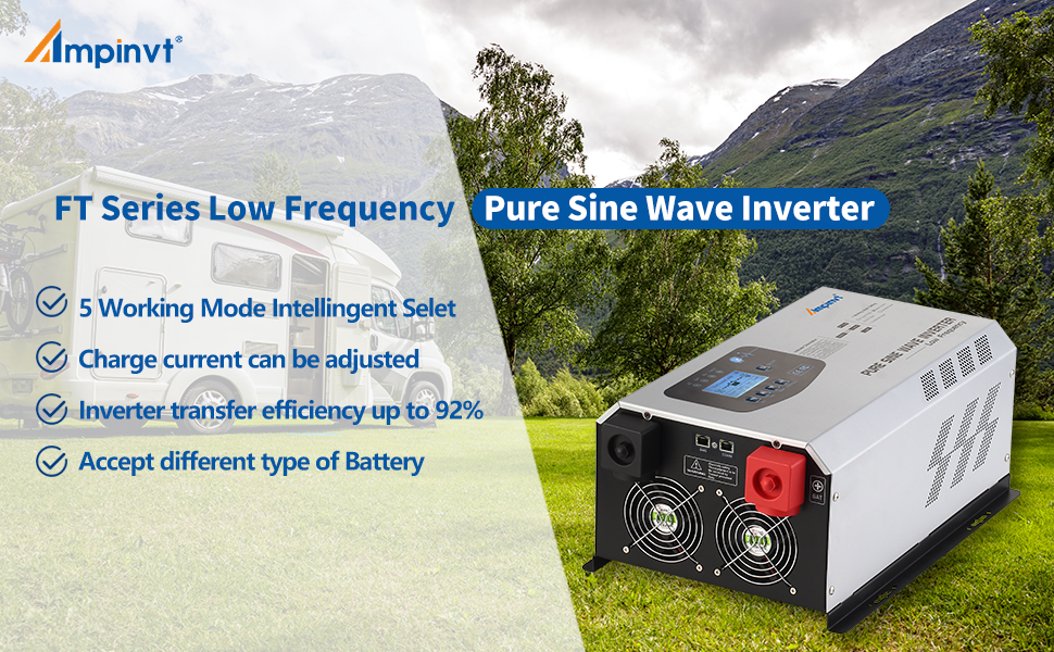
Image: Key features of the Ampinvt FT Series Low Frequency Pure Sine Wave Inverter, highlighting 5 working modes, adjustable charge current, high transfer efficiency, and multi-battery compatibility.
4. Product Components
The Ampinvt FT-3000W24V inverter features a user-friendly design with clearly labeled connection points and an intuitive control panel.

Image: Front view of the Ampinvt FT-3000W24V Pure Sine Wave Inverter, showing the LCD display, control buttons, and AC output sockets.
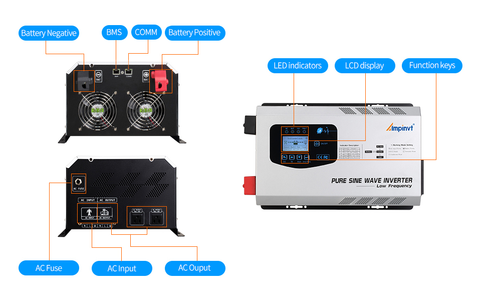
Image: Detailed overview of the inverter's front and rear panels, indicating LED indicators, LCD display, function keys, battery terminals (negative and positive), BMS port, COMM port, AC fuse, AC input, and AC output.
Front Panel:
- LCD Display: Shows real-time operational status, battery voltage, output voltage, load percentage, and selected working mode.
- Control Buttons: Used for navigation and setting adjustments (ESC, Up, Down, Enter/Menu, ON/OFF).
- LED Indicators: Provide quick visual status for AC, Battery, Inverter, and Fault conditions.
Rear Panel:
- Battery Terminals: Clearly marked positive (+) and negative (-) terminals for 24V DC battery connection.
- AC Input Terminal: For connecting to utility grid or generator AC power.
- AC Output Terminals/Sockets: For connecting AC loads.
- Ground Terminal: For safety grounding.
- Cooling Fans: Integrated fans for thermal management.
- BMS/COMM Port: For communication with Battery Management Systems or remote monitoring.
5. Setup and Installation
Proper installation is crucial for the safe and efficient operation of your inverter. Follow these steps carefully.
5.1 DC Battery Connection
- Prepare Cables: Use the factory standard cables provided. Ensure the cables are of appropriate gauge for your battery system and inverter wattage.
- Remove Terminal Screws: Unscrew and remove the nuts and washers from the battery input terminals on the inverter.
- Connect Battery Cables:
- Connect the red cable to the inverter's positive (+) terminal and the battery's positive (+) terminal.
- Connect the black cable to the inverter's negative (-) terminal and the battery's negative (-) terminal.
Tip: When wiring, quickly tap the terminal with the terminal lug, or connect the mains first, which can effectively avoid sparks.
- Secure Connections: Tighten the nuts firmly on both the inverter and battery terminals. Place the insulation caps over the terminals.
- Verify Polarity: Double-check that positive is connected to positive and negative to negative. Reverse connection is forbidden and will damage the unit.
Video: This video demonstrates the connection guide for a VEVOR Inverter Charger, which includes similar battery connection steps. Ensure to follow the specific instructions for your Ampinvt FT-3000W24V model.

Image: Illustration showing various battery types supported by the inverter, including Flooded, GEL, AGM, Lithium, and LiFePO4, along with the 24V battery voltage requirement and adjustable charging current.
5.2 AC Input/Output Connection
The inverter has dedicated terminals for AC input (from utility or generator) and AC output (to loads). Always ensure the mains power is off before making these connections.
- Access AC Terminals: Remove the screws and open the black cover on the side of the inverter to access the AC input and output terminals.
- Connect AC Output: Install the output cable to the designated OUTPUT terminals.
- Connect AC Input: Connect the AC input connection line to the designated INPUT terminals.
- Wire Polarity: Connect the 'L' (Live) wire to the live terminal and the 'N' (Neutral) wire to the neutral terminal. Ensure proper grounding.
- Secure Cover: Once all connections are secure, replace the black cover and tighten the screws.

Image: Connection diagram illustrating the setup with solar panels, MPPT solar charge controller, battery, inverter, utility grid, generator, and connected appliances.
6. Operating Modes
The Ampinvt FT-3000W24V inverter offers five distinct working modes to optimize power usage based on your needs. These modes can be configured via the LCD display.
- AC Priority Mode: In this mode, the inverter primarily uses AC power from the utility grid or generator to supply connected loads. It also charges the battery automatically. If AC input is lost, the inverter seamlessly switches to battery power.
- Battery Priority Mode: This mode prioritizes power from the battery. The inverter will draw power from the battery to supply loads. If the battery voltage drops below a set low voltage protection threshold, it will switch to utility power. Once the battery is sufficiently charged, it will revert to battery power. This mode includes configurable low voltage restore and protect settings.
- ECO Mode: Designed for energy saving, the inverter will automatically enter a low-power sleep state and stop output if the connected load is less than 10% of its capacity. When the load increases above 10%, it will automatically resume normal inversion.
- Generator Mode: This mode is used when connecting an unstable 120V generator. The inverter's built-in AVR regulates the generator's AC input, automatically matching 50Hz/60Hz frequency, to provide a stable output voltage within the normal operating range.
- Unattended Mode: Similar to Battery Priority, but with enhanced automation. When the battery voltage is low, the inverter enters a power-saving standby state. It will automatically restore normal output once the battery voltage reaches a user-defined restoration level (e.g., after solar charging), allowing for fully automatic, unattended operation. This mode also features low voltage restore and protect settings.
Video: This video provides an overview of the Ampinvt 2000W 3000W off-grid inverter charger, demonstrating its features and potentially its operating modes.
7. Operation
7.1 Powering On/Off
- To Power On: After all connections are secure, press the ON/OFF button on the front panel. The LCD display will illuminate, and the inverter will initiate its startup sequence.
- To Power Off: Press and hold the ON/OFF button until the display turns off. Disconnect loads before powering off for safety.
7.2 LCD Display and Settings
The LCD display provides real-time information and allows for configuration of various parameters. Use the ESC, Up, Down, and Enter/Menu buttons to navigate and adjust settings.
- Monitoring: The display shows input/output voltage, frequency, battery status, load level, and current operating mode.
- Accessing Settings: Press and hold the "Enter/Menu" button for 3 seconds to enter the main settings interface.
- Adjusting Parameters: Use the "Up" and "Down" buttons to scroll through options and "Enter/Menu" to select or confirm.
- Battery Type Selection: Configure the inverter for your specific battery type (SLA, AGM, GEL, Li-ion, LiFePO4, or custom settings) to ensure optimal charging and discharge protection.
- Charging Current Adjustment: Adjust the battery charging current (0-35A) as needed.
Video: This video demonstrates parameter settings for an Ampinvt low frequency inverter, which may share similar interface and setting procedures with your FT-3000W24V model.
7.3 Connecting Loads
Connect your AC appliances to the output sockets or terminals. Ensure the total wattage of connected devices does not exceed the inverter's continuous output capacity of 3000W.
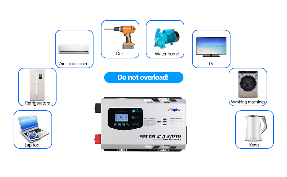
Image: Visual reminder to avoid overloading the inverter, showing various household appliances that can be powered, such as air conditioners, drills, water pumps, TVs, refrigerators, washing machines, laptops, and kettles.
8. Maintenance
Regular maintenance ensures the longevity and optimal performance of your Ampinvt inverter.
- Clean Regularly: Keep the inverter's exterior clean and free from dust and debris. Ensure ventilation openings are not blocked.
- Check Connections: Periodically inspect all electrical connections (DC and AC) for tightness and corrosion. Loose connections can lead to overheating and poor performance.
- Battery Health: Monitor your battery's health and charge level. Ensure it is compatible with the inverter's settings.
- Environmental Conditions: Ensure the inverter is operated within its specified temperature and humidity ranges. Avoid direct sunlight and excessive moisture.
- Fan Operation: Ensure cooling fans are operating correctly and are not obstructed.
9. Troubleshooting
If you encounter issues with your inverter, refer to the following common problems and solutions:
| Problem | Possible Cause | Solution |
|---|---|---|
| Inverter not turning on | Loose battery connections, low battery voltage, faulty ON/OFF switch. | Check and tighten battery connections. Charge the battery. Ensure the ON/OFF button is pressed correctly. |
| No AC output | Overload, short circuit, high/low battery voltage, inverter fault. | Reduce load. Check for short circuits in connected appliances. Check battery voltage and charge if low. Refer to LCD fault codes. |
| Overload alarm/shutdown | Connected load exceeds inverter capacity. | Reduce the total wattage of connected appliances. Ensure peak surge requirements are within limits. |
| Battery not charging | AC input not present, charging current set to 0A, battery fault. | Verify AC input connection. Check charging current setting on LCD. Inspect battery health. |
| Inverter operating in unexpected mode | Incorrect mode selection. | Access the settings menu via the LCD display and select the desired operating mode. |
10. Specifications
| Feature | Detail |
|---|---|
| Model | FT-3000W24V |
| Continuous Output Power | 3000W |
| Peak Output Power | 9000W |
| DC Input Voltage | 24V |
| AC Output Voltage | 120V |
| AC Output Frequency | 50Hz/60Hz (Auto-matching) |
| Output Waveform | Pure Sine Wave |
| Transfer Efficiency | >90% |
| Adjustable Charging Current | 0-35A |
| Product Dimensions | 10 x 5.1 x 12.2 inches |
| Item Weight | 19 pounds |
| Supported Battery Types | SLA, AGM, GEL, Li-ion, LiFePO4 (Customizable) |
11. Warranty and Support
For warranty information, technical support, or service inquiries, please refer to the documentation included with your product or contact Ampinvt customer service. Keep your purchase receipt for warranty claims.


