1. Introduction
The YIWENG YH-TC01 is a multi-function digital tachometer designed for precise speed measurement and counting. It features a high-accuracy LED digital display and utilizes a Hall sensor for reliable detection. This device is suitable for various mechanical equipment requiring rotational speed measurement, such as harvesters, machine tools, motors, and fans, as well as for production counting applications.
Key features include:
- Multi-function speed measuring/counting meter with an upper limit alarm output function.
- Compatible with Hall switch, metal proximity switch, and other detection switch signals.
- Outputs a channel of NPN alarm signal, allowing connection to indicator lights or sounders for customizable warnings.
- The supporting three-wire sensor offers high sensitivity, strong reliability, and excellent anti-interference performance for stable long-term operation.

Figure 1.1: Front view of the YH-TC01 Digital Tachometer, showing the LED display and control buttons.
2. Specifications
The YH-TC01 Digital Tachometer is designed with the following technical specifications:
| Parameter | Value |
|---|---|
| Working Voltage | DC 9-24V |
| Basic Speed Range (Single Detection Point) | 30-80000 rpm |
| Effective Speed Range | Basic range / Number of detection points (minimum 10 rpm) |
| Count Range | 1-9999 |
| Error Range | ± 1% |
| Refresh Rate | >1 time/second |
| Display | 4-bit 0.56-inch LED |
| Hole Size | 76.5 x 39.5 mm |
| Item Size | 78 x 42 x 24 mm |
| Package Size | 130 x 80 x 45 mm |
| Package Weight | 100g |
| Working Temperature | 0 to 60℃ (relative humidity below 80%) |

Figure 2.1: Side view of the YH-TC01 Digital Tachometer, showing printed specifications.

Figure 2.2: Dimensional drawing of the YH-TC01 Digital Tachometer (measurements in mm).
3. Setup and Installation
Proper installation of the Hall sensor is crucial for accurate speed detection. The sensor detects magnetic pulses from a rotating object, such as a gear or a disk with magnets.
3.1 Sensor Installation
The Hall sensor should be mounted securely near the rotating part. The distance between the sensor and the magnet(s) on the rotating object is critical for reliable detection, typically within 1-10mm.
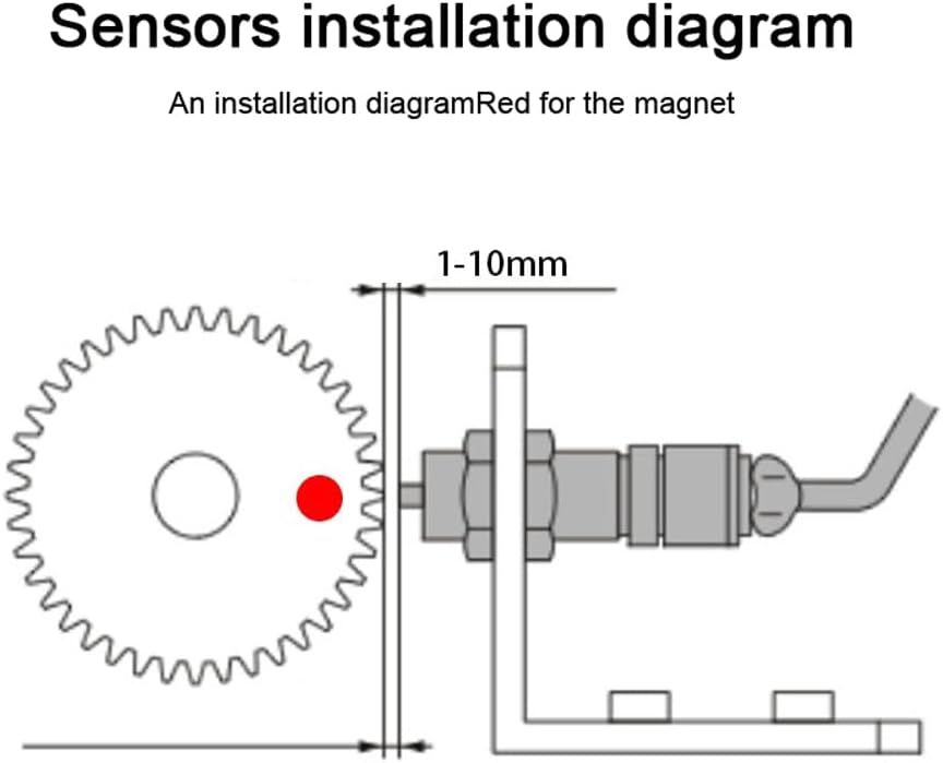
Figure 3.1: Sensor installation diagram with a single magnet on a rotating gear. The red dot indicates the magnet position.
For improved accuracy, especially at lower speeds or for specific applications, multiple detection points (magnets) can be used. The tachometer's internal program allows for setting multiple detection points with a single probe.

Figure 3.2: Sensor installation diagram with three magnets on a rotating gear. The red dots indicate magnet positions.
3.2 Wiring Diagram
The YH-TC01 tachometer and its Hall sensor require proper electrical connection. Refer to the wiring diagram below for correct power and signal connections.

Figure 3.3: Power and sensor wiring diagram. Ensure correct polarity for DC 9-24V input and NPN alarm signal output.
The supporting sensor is a three-wire type. Connect the wires according to the diagram. The tachometer also provides an NPN alarm signal output, which can be connected to an external indicator light or sounder for warning purposes.

Figure 3.4: Overview of YH-TC01 components: digital tachometer, Hall sensor, magnet, and connecting wires.
4. Operating Instructions
The YH-TC01 Digital Tachometer offers speed measurement, counting, and alarm functions. The device uses a 4-bit LED display to show readings.
4.1 Speed Measurement
Once powered on and the sensor is correctly installed and detecting pulses, the device will display the rotational speed (RPM). The speed measurement employs a multi-period average method for accuracy across a wide range of speeds.
- Ensure the sensor-to-magnet distance is within the optimal range (1-10mm).
- The display will update at a refresh rate of more than 1 time per second.
- If multiple magnets are used, the device's internal settings must be configured to reflect the number of detection points for accurate RPM calculation. Refer to the device's specific programming instructions (not detailed in this manual) for adjusting these settings.
4.2 Counting Function
The device can also function as a counter, with a range of 1-9999. This function is realized by the external counting capability of the single-chip timer, ensuring stability and reliability.
- The counting mode can typically be toggled using the control buttons on the front panel (refer to Figure 1.1).
- Each pulse detected by the sensor contributes to the count.
- Specific instructions for resetting the count or switching between speed/count modes are usually found in the device's detailed programming guide.
4.3 Alarm Output Function
The YH-TC01 includes an upper limit alarm output. Users can customize the alarm field values (thresholds) and connect external indicators or sounders to the NPN alarm signal output.
- To set the alarm threshold, access the device's programming menu using the front panel buttons.
- When the measured speed or count exceeds the set upper limit, the NPN alarm output will activate.
- Ensure any external alarm devices are compatible with an NPN signal.
5. Maintenance
To ensure the longevity and accurate operation of your YH-TC01 Digital Tachometer, follow these maintenance guidelines:
- Cleaning: Keep the display and casing clean using a soft, dry cloth. Avoid abrasive cleaners or solvents that could damage the plastic.
- Sensor Inspection: Periodically check the Hall sensor and its mounting for any signs of damage, corrosion, or misalignment. Ensure the sensor-to-magnet gap remains consistent.
- Wiring: Inspect all wiring connections for looseness or damage. Secure any loose connections to prevent intermittent operation.
- Environmental Conditions: Operate the device within the specified working temperature and humidity ranges (0 to 60℃, relative humidity below 80%) to prevent malfunction.
6. Troubleshooting
If you encounter issues with your YH-TC01 Digital Tachometer, consider the following common troubleshooting steps:
- No Display/Power:
- Check the power supply (DC 9-24V) and ensure it is correctly connected and providing the specified voltage.
- Verify all power wiring connections are secure.
- Inaccurate Speed Reading:
- Ensure the Hall sensor is correctly aligned with the magnet(s) on the rotating object.
- Verify the sensor-to-magnet distance is within the recommended 1-10mm range.
- If multiple magnets are used, confirm that the device's internal settings for the number of detection points are correctly configured.
- Check for any interference from strong magnetic fields or electrical noise near the sensor.
- No Counting/Speed Detection:
- Inspect the sensor wiring for breaks or loose connections.
- Ensure the sensor itself is functional (if possible, test with another known working sensor).
- Verify that the rotating object has a magnet and that the sensor is detecting it.
- Alarm Not Functioning:
- Check the alarm threshold settings in the device's configuration.
- Verify the wiring to the external alarm device and ensure it is compatible with an NPN signal.
- Confirm that the measured value is actually exceeding the set alarm threshold.
If these steps do not resolve the issue, please contact customer support for further assistance.
7. Warranty and Support
Warranty Information: Specific warranty terms and conditions for the YIWENG YH-TC01 Digital Tachometer may vary depending on your region and point of purchase. Please refer to the documentation provided at the time of purchase or contact your seller directly for detailed warranty information.
Customer Support: For technical assistance, troubleshooting beyond the scope of this manual, or inquiries regarding your product, please contact YIWENG customer support or your authorized dealer. When contacting support, please have your product model (YH-TC01) and purchase details readily available.