1. Introduction
This instruction manual provides essential information for the proper installation, operation, and maintenance of your ToiCottage JR1858RXS-7P Remote Control Motherboard. This component is designed as a replacement part for children's electric ride-on vehicles. Please read this manual thoroughly before installation and use to ensure safe and correct functionality.
2. Safety Information
Always prioritize safety when handling and installing electronic components. Ensure the electric vehicle is powered off and disconnected from its power source before beginning any installation or maintenance. This product is intended for use in children's electric vehicles. Keep small parts away from young children to prevent choking hazards. If you are unsure about any installation step, consult a qualified technician.
3. Package Contents
Verify that all items are present in the package:
- 1 x JR1858RXS-7P Remote Control Motherboard
4. Product Overview
The JR1858RXS-7P is a replacement motherboard for the control system of children's electric ride-on vehicles. It features a 7-pin socket for connection to the vehicle's wiring harness. Ensure the appearance and socket configuration of this replacement part match your original component before installation.
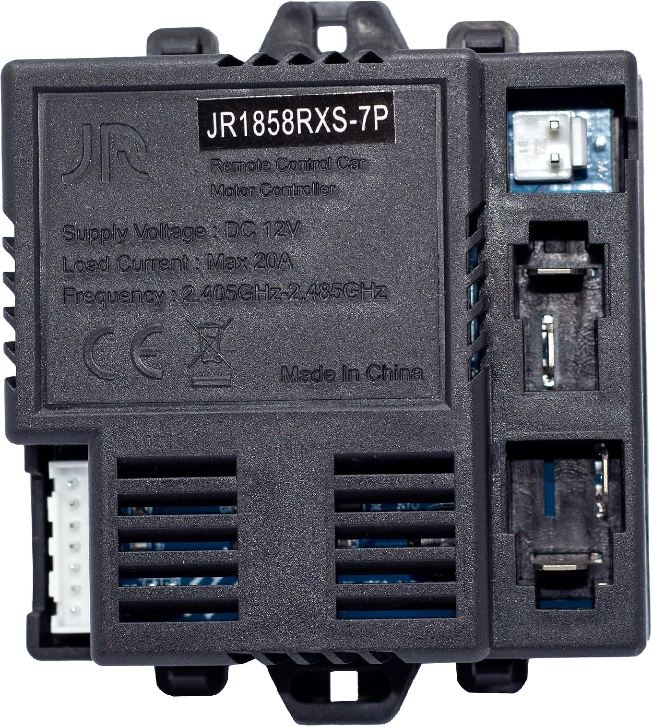
Figure 4.1: Top view of the JR1858RXS-7P motherboard. This image displays the main body of the motherboard with the model number "JR1858RXS-7P" clearly visible, along with specifications such as "Supply Voltage: DC 12V", "Load Current: Max 20A", and "Frequency: 2.405GHz-2.485GHz". A 7-pin white connector is visible on the left side.

Figure 4.2: Detailed view highlighting the model number and 7-pin socket. This image specifically points out the "JR1858RXS-7P" model number on the label and indicates the 7-pin white connector on the left side of the motherboard, crucial for compatibility verification.
5. Setup and Installation
This motherboard is a direct replacement part. Follow these steps for installation:
- Power Disconnection: Before starting, ensure the electric vehicle's battery is disconnected to prevent electrical hazards.
- Locate Original Motherboard: Identify the existing remote control motherboard in your child's electric vehicle. Note its mounting position and how it is connected.
- Verify Compatibility: Carefully compare the appearance and, most importantly, the socket configuration (especially the 7-pin socket) of the new JR1858RXS-7P motherboard with your original part. Incompatibility can lead to malfunction.
- Remove Original Motherboard: Disconnect all wiring harnesses from the old motherboard. Carefully unmount it from the vehicle.
- Install New Motherboard: Mount the new JR1858RXS-7P motherboard in the same location as the original.
- Connect Wiring: Reconnect all wiring harnesses to the new motherboard, ensuring each connector is securely seated in its correct port. Pay special attention to the 7-pin connector.
- Reconnect Battery: Once all connections are secure, reconnect the vehicle's battery.
6. Operating Instructions: Remote Control Pairing
After replacing the motherboard, the remote control needs to be re-matched (paired) with the new receiver. The exact pairing procedure may vary slightly depending on the specific remote control model. Generally, the steps are as follows:
- Power On Vehicle: Turn on the electric vehicle's power switch.
- Initiate Pairing on Remote: On your remote control, press and hold the pairing button (often labeled "Code", "Pair", or a similar icon). Hold it for several seconds until an indicator light on the remote starts flashing.
- Observe Vehicle Indicator: While the remote's light is flashing, an indicator light on the vehicle (or the new motherboard) should also flash or change state, indicating it is searching for a signal.
- Confirm Pairing: Once successfully paired, the indicator light on the remote control should stop flashing and remain solid, and the vehicle should respond to remote commands.
- Test Functionality: Test all remote control functions (forward, backward, left, right, speed settings) to ensure proper operation.
If pairing fails, repeat the steps. Refer to your specific remote control's manual for precise pairing instructions if these general steps are unsuccessful.
7. Maintenance
To ensure the longevity and proper functioning of your JR1858RXS-7P motherboard:
- Keep Dry: Protect the motherboard from moisture and liquids. Water damage can cause irreversible malfunction.
- Avoid Extreme Temperatures: Do not expose the motherboard to extreme heat or cold, as this can affect electronic components.
- Clean Gently: If cleaning is necessary, use a soft, dry cloth. Do not use harsh chemicals or abrasive materials.
- Secure Connections: Periodically check that all wiring connections are secure and free from corrosion.
8. Troubleshooting
If you encounter issues after installing the JR1858RXS-7P motherboard, consider the following:
- Vehicle Not Responding to Remote:
- Ensure the remote control batteries are charged and correctly inserted.
- Re-attempt the pairing process as described in Section 6.
- Check all wiring connections to the motherboard for looseness or incorrect placement.
- Vehicle Not Powering On:
- Verify the vehicle's main battery is charged and properly connected.
- Check the main power switch of the vehicle.
- Ensure all power-related connections to the motherboard are secure.
- Intermittent Functionality:
- Inspect wiring for any signs of damage or loose connections.
- Ensure the motherboard is securely mounted and not subject to excessive vibration.
If problems persist, contact customer support for further assistance.
9. Specifications
| Feature | Detail |
|---|---|
| Model Number | JR1858RXS-7P |
| Supply Voltage | DC 12V |
| Load Current | Max 20A |
| Frequency | 2.405GHz-2.485GHz |
| Product Dimensions | 3.4 x 1.2 x 2.87 inches |
| Item Weight | 2.29 ounces |
| Manufacturer | Toi Cottage |
| Recommended Age | 18 months - 5 years (for compatible vehicles) |
10. Warranty and Support
For warranty information or technical support regarding your ToiCottage JR1858RXS-7P Remote Control Motherboard, please contact ToiCottage customer service. Keep your purchase receipt as proof of purchase. You can often find contact information on the product packaging or the retailer's website where the product was purchased.
For more replacement parts, you can search for "ToiCottage" on relevant retail platforms.


