1. Introduction
This manual provides essential information for the safe and effective installation, operation, and maintenance of your AMBITIONMOTOR VIB200 Broadcast Spreader Vibrator Kit. Please read this manual thoroughly before using the product and retain it for future reference. The VIB200 vibrator is designed to provide 200 lbs of force, ensuring a smooth and even spread by breaking apart clumps in materials such as salt or ice melt, allowing them to flow freely from the hopper.
2. Safety Information
Always observe the following safety precautions to prevent injury or damage to the product.
- Electrical Safety: Ensure the power source is disconnected before installation or maintenance. The unit operates on 12VDC. Use appropriate wiring and a 15A fuse as recommended to prevent electrical overload.
- Installation: Mount the vibrator securely to prevent it from dislodging during operation. Ensure all connections are tight and properly insulated.
- Operation: Keep hands and loose clothing away from moving parts during operation. Do not operate the vibrator if it is damaged or improperly installed.
- Maintenance: Only perform maintenance when the unit is disconnected from power. Refer to the maintenance section for proper procedures.
3. Package Contents
Verify that all components are present in the package before beginning installation.
- 1 x VIB200 Vibrator
- 4 x Hex Stainless Steel Nylon Nuts
- 4 x Hex Stainless Steel Nuts
- 4 x Hex Stainless Steel Bolts
- 1 x Stainless Steel Backing Plate

Image 3.1: Overview of the VIB200 Broadcast Spreader Vibrator Kit components.

Image 3.2: Included stainless steel backing plate.
4. Specifications
The following table details the technical specifications of the VIB200 Vibrator Kit.
| Feature | Specification |
|---|---|
| Vibration Force | 200 LB |
| Vibration Frequency | 75 Hz |
| Voltage | 12 Volts DC |
| Load Current | 10 A |
| Power (Horsepower) | 80 Watts |
| Speed | 4500 RPM |
| Connector Type | SAE J928-II PIN |
| Cable Length | 42 inches (14AWG) |
| Product Dimensions (LxWxH) | 6.4" x 5" x 3.72" |
| Mounting Dimensions | 4" x 2" | Ø0.43" |
| Sealing Performance | IP67 |
| Salt Spray Test Rating | 96 hours |
| Duty Cycle | Continuous |
| Brush Lifetime | At least 1200 hours |
Note: It is recommended to use this product with a 15A fuse.
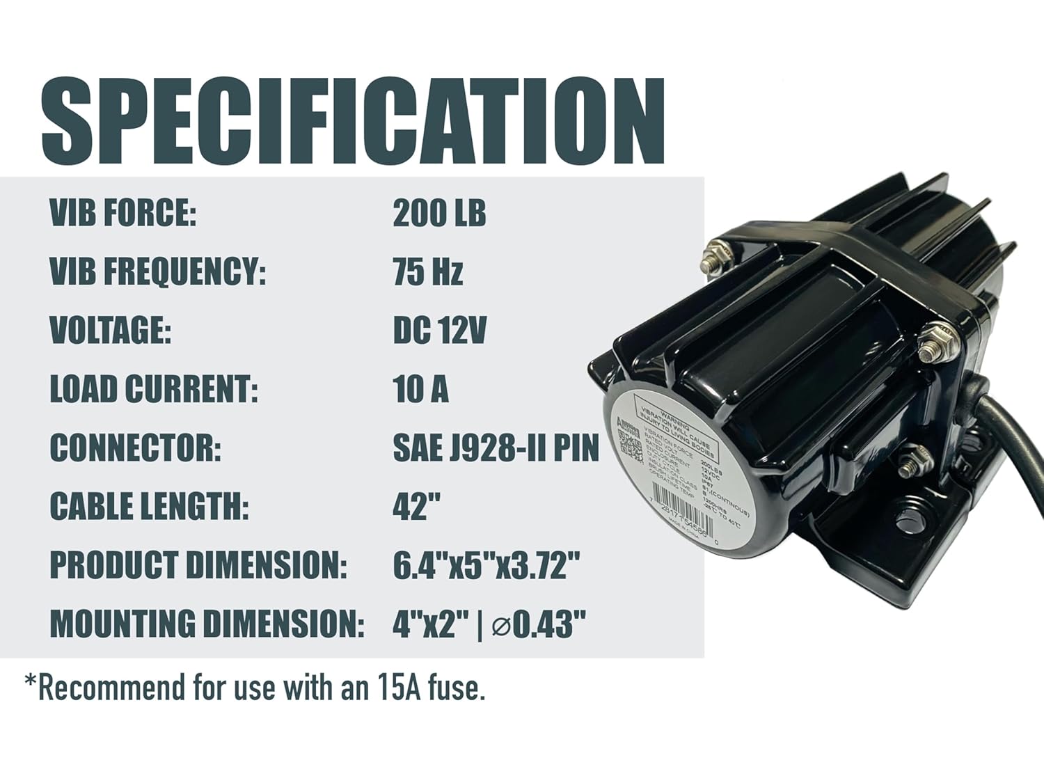
Image 4.1: Visual representation of key specifications for the VIB200 vibrator.

Image 4.2: Detailed view of the vibrator's rugged cast aluminum housing, strong one-piece base, and SAE two-pole quick connector.

Image 4.3: Technical drawing illustrating the dimensions of the VIB200 vibrator.
5. Setup and Installation
Follow these steps for proper installation of the VIB200 vibrator on your V-box spreader.
- Prepare Mounting Surface: Identify a suitable, flat mounting location on your spreader's hopper, typically near the bottom, where vibration will be most effective. Ensure the surface is clean and free of debris.
- Position Backing Plate: Place the stainless steel backing plate (Item 19 in Image 5.1) on the inside of the hopper wall at the desired mounting location.
- Align Vibrator: Position the VIB200 vibrator (Item 22 in Image 5.1) on the outside of the hopper wall, aligning its mounting holes with the holes in the backing plate.
- Secure with Hardware: Insert the provided hex stainless steel bolts through the vibrator, hopper wall, and backing plate. Secure them with the hex stainless steel nuts and nylon nuts (Item 33 in Image 5.1) on the inside of the hopper. Tighten all fasteners securely to prevent loosening from vibration.
- Electrical Connection: Connect the 14AWG 42" cable with the SAE J928 2 PIN connector to a 12VDC power source. Ensure the power source is fused with a 15A fuse. Observe correct polarity.
- Cable Management: Route the power cable safely, away from moving parts, sharp edges, and heat sources. Secure it with cable ties if necessary.

Image 5.1: Diagram illustrating the mounting of the VIB200 vibrator (22) with the backing plate (19) and fasteners (33) on a spreader hopper.
6. Operating Instructions
Once the VIB200 vibrator is correctly installed and connected to a 12VDC power source, follow these steps for operation:
- Fill Hopper: Load your V-box spreader with the desired material (e.g., salt, ice melt).
- Activate Vibrator: Turn on the power switch connected to the vibrator. The unit will begin to vibrate, shaking the hopper.
- Monitor Material Flow: Observe the material flow from the spreader. The vibration helps to break up clumps and ensure a consistent, even spread.
- Deactivate Vibrator: Turn off the power switch to the vibrator when spreading is complete or when the hopper is empty.
The VIB200 is designed for continuous duty cycle, providing reliable performance during extended use.
7. Maintenance
Regular maintenance ensures the longevity and optimal performance of your VIB200 vibrator.
- Periodic Inspection: Regularly inspect the vibrator for any signs of damage, loose fasteners, or wear. Check the power cable for cuts, abrasions, or frayed wires.
- Cleanliness: Keep the exterior of the vibrator clean. Remove any accumulated dirt, salt, or debris, especially around the mounting area and cable connections.
- Electrical Connections: Ensure all electrical connections remain tight and free from corrosion. Apply dielectric grease to connectors if operating in corrosive environments.
- Fastener Check: Periodically re-tighten all mounting bolts and nuts, as vibration can cause them to loosen over time.
- Storage: When not in use for extended periods, store the vibrator in a clean, dry environment.
8. Troubleshooting
Refer to the table below for common issues and their potential solutions.
| Problem | Possible Cause | Solution |
|---|---|---|
| Vibrator does not operate | No power supply | Check power switch, battery connection, and ensure 12VDC is supplied. |
| Vibrator operates intermittently | Loose electrical connection | Inspect and tighten all cable connections, especially the SAE J928 connector. |
| Vibrator is weak or ineffective | Insufficient voltage or current | Verify 12VDC power supply. Check for undersized wiring or a blown fuse. Ensure a 15A fuse is used. |
| Excessive noise or unusual sounds | Loose mounting hardware | Tighten all mounting bolts and nuts. Ensure the vibrator is securely attached to the spreader. |
| Vibrator overheats | Prolonged operation in extreme conditions or internal fault | Allow unit to cool. Ensure adequate ventilation. If problem persists, discontinue use and contact support. |
9. Warranty and Support
For warranty information or technical support, please contact AMBITIONMOTOR customer service. Keep your purchase receipt as proof of purchase. Our team is available to assist with any questions or issues you may encounter with your VIB200 Broadcast Spreader Vibrator Kit.
Contact Information: Refer to the AMBITIONMOTOR official website or your purchase documentation for the most current support contact details.