1. Product Overview
The Pro'sKit MT-2017N is a protective function analog multimeter designed for accurate and safe electrical measurements. It features a mirrored aluminum dial, a robust protective holster, a built-in stand, and a hook-up design for convenience. This manual provides detailed instructions for its setup, operation, and maintenance.

Image 1.1: Front view of the Pro'sKit MT-2017N Analog Multimeter.
2. Key Features
- Protective Function Analog Multimeter: Designed for durability and safety.
- Mirrored Aluminum Dial: Ensures clear and accurate readings.
- Robust Protective Holster: Provides enhanced protection against drops and impacts.
- Built-in Stand and Hook-up Design: Offers convenient hands-free operation.
- Precise Measurement: Delivers highly accurate measurement results.
- Overload Protection: Integrated safety features to prevent damage from excessive current or voltage.
- Gilded Test Leads: High-quality test leads for reliable connections and accurate readings.

Image 2.1: Overview of the multimeter's protective features and capabilities.

Image 2.2: Detailed view of the multimeter's internal design for precise measurements.
3. Components and Controls
Familiarize yourself with the various parts and controls of your MT-2017N multimeter for effective operation.

Image 3.1: Labeled diagram of the multimeter's key components.
- Clear Analog Panel: Displays DCV, DCA, ACV, Resistance, Triode, Diode, LED, Battery, Capacitance, and NULL DCV readings.
- Pointer Return to Zero: Ensures accurate starting point for measurements.
- Function Selection Dial: Used to select the desired measurement mode, with fuse protection.
- Ω Zero Adjustor: For calibrating resistance measurements.
- COM Socket: Common input terminal for all measurements.
- Vm AΩ+ Socket: Positive input terminal for voltage, current, and resistance measurements.
- 10A Socket: Dedicated input for high current (10A) measurements.

Image 3.2: Features like clear reading, buzzer for continuity, and protective rubber casing.

Image 3.3: Accessories and design elements for convenience and maintenance.
4. Setup
4.1 Battery Installation
The MT-2017N requires 1 Lithium Metal battery (included) for operation. To install or replace batteries:
- Locate the battery compartment on the back of the multimeter.
- Use a screwdriver to loosen the screw-on lock securing the battery cover.
- Remove the battery cover.
- Insert the 9V and 1.5V AAA batteries according to the polarity indicators inside the compartment.
- Replace the battery cover and tighten the screw-on lock.

Image 4.1: Battery compartment and internal protection features.
4.2 Test Lead Connection
Connect the gilded test leads to the appropriate input jacks on the multimeter based on the measurement you intend to perform. Always connect the black lead to the 'COM' (common) jack.
5. Operating Instructions
Before taking any measurements, ensure the multimeter is set to the correct function and range. Refer to the specific measurement type below.
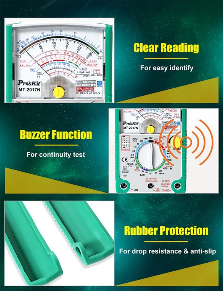
Image 5.1: Examples of different measurement applications.
5.1 DC Voltage (DCV) Measurement
- Set the function dial to the desired DCV range (e.g., 10, 50, 250, 1000V).
- Connect the black test lead to the 'COM' jack and the red test lead to the 'Vm AΩ+' jack.
- Connect the test leads in parallel across the DC voltage source.
- Read the voltage value on the DCV scale of the analog display.
5.2 AC Voltage (ACV) Measurement
- Set the function dial to the desired ACV range (e.g., 10, 50, 250, 1000V).
- Connect the black test lead to the 'COM' jack and the red test lead to the 'Vm AΩ+' jack.
- Connect the test leads in parallel across the AC voltage source.
- Read the voltage value on the ACV scale of the analog display.
5.3 Resistance (Ω) Measurement
- Set the function dial to the desired Ω range (e.g., X1, X10, X100, X1K, X10K).
- Connect the black test lead to the 'COM' jack and the red test lead to the 'Vm AΩ+' jack.
- Before measuring, short the test leads together and adjust the 'Ω ADJ' knob to set the pointer to zero on the resistance scale.
- Connect the test leads across the component whose resistance you want to measure. Ensure the component is de-energized.
- Read the resistance value on the Ω scale and multiply by the selected range multiplier.
5.4 DC Current (DCA) Measurement
- Set the function dial to the desired DCA range (e.g., 2.5mA, 25mA, 250mA, 10A).
- For ranges up to 250mA, connect the black test lead to 'COM' and the red test lead to 'Vm AΩ+'. For 10A measurements, connect the red test lead to the '10A' jack.
- Connect the multimeter in series with the circuit where you want to measure current.
- Read the current value on the DCA scale.
5.5 Capacitance Measurement
- Set the function dial to the 'C(µF)' range.
- Connect the black test lead to 'COM' and the red test lead to 'Vm AΩ+'.
- Discharge the capacitor before connecting the test leads across it.
- Read the capacitance value on the appropriate scale.
5.6 Battery Check
- Set the function dial to the 'BATT' range (1.5V or 9V).
- Connect the black test lead to 'COM' and the red test lead to 'Vm AΩ+'.
- Connect the test leads across the battery terminals, observing polarity.
- Read the battery voltage on the corresponding scale.
5.7 Buzzer Function (Continuity Test)
- Set the function dial to the 'Buzzer' position.
- Connect the black test lead to 'COM' and the red test lead to 'Vm AΩ+'.
- Touch the test leads to the two points of the circuit or component you want to test for continuity.
- If there is continuity (low resistance), the multimeter will emit an audible beep.
6. Maintenance
Proper maintenance ensures the longevity and accuracy of your multimeter.
6.1 Cleaning
- Wipe the multimeter's casing with a damp cloth. Do not use abrasive cleaners or solvents.
- Keep the test leads clean and free of debris.
6.2 Fuse Replacement
The MT-2017N is equipped with 0.5A/250V and 10A/250V fuses for overload protection. If the multimeter stops functioning on a particular range, the fuse may need replacement.
- Ensure the multimeter is turned off and test leads are disconnected.
- Open the battery compartment as described in Section 4.1.
- Carefully remove the old fuse(s).
- Replace with new fuses of the exact same type and rating (0.5A/250V and 10A/250V).
- Close the battery compartment securely.
Image 6.1: Location of fuses within the multimeter's battery compartment.
6.3 Storage
- Store the multimeter in a cool, dry place away from direct sunlight and extreme temperatures.
- If storing for extended periods, remove the batteries to prevent leakage.
7. Troubleshooting
If you encounter issues with your MT-2017N, refer to the table below for common problems and solutions.
| Problem | Possible Cause | Solution |
|---|---|---|
| No display/Power off | Dead or incorrectly installed batteries. | Check battery polarity, replace batteries. |
| No reading on a specific range | Blown fuse for that range. | Replace the appropriate fuse (0.5A or 10A). |
| Inaccurate resistance reading | Ω Zero Adjustor not calibrated. | Short test leads and adjust Ω ADJ knob to zero. |
| No continuity beep | Open circuit or high resistance. | Verify circuit integrity. |
| Pointer not returning to zero | Mechanical issue or impact. | Gently tap the meter or seek professional service if persistent. |
8. Technical Specifications
Detailed specifications for the Pro'sKit MT-2017N Analog Multimeter.
| Specification | Value |
|---|---|
| Model Number | YH-MT-2017N-C |
| Product Dimensions | 7.87 x 3.94 x 5.91 inches |
| Item Weight | 1 Kilogram (2.2 Pounds) |
| Batteries | 1 Lithium Metal battery required (included) |
| Manufacturer | Pro'sKit |
| Country of Origin | China |
| Color | Multicoloured (Green/Black) |
| Safety Compliance | CE, RoHS, CAT II 1000V, CAT III 500V |
| DC Voltage (DCV) | 0.1/2.5/10/50/250/1000V ±4.0%FSD |
| AC Voltage (ACV) | 10/50/250/1000V ±5.0%FSD |
| DC Current (DCA) | 50µ/2.5m/25m/250mA ±3.0%FSD, 10A ±4.0%FSD |
| Resistance (Ω) | X1/X10/X100/X1K/X10K (20MΩ) ±4.0%ARC of scale length |
| Capacitance | C(µF) X1 (200µF Approx.) Max |
| Battery Check | 1.5V/9V |
| Diode & LED Test | Yes |
| Continuity with Buzzer | Yes |
| Transistor Check | Yes |
| Power Source | 9V (6F22) x 1, 1.5V (AAA) x 2 |
9. Warranty and Support
Pro'sKit products are manufactured to high-quality standards. For warranty information and customer support, please refer to the documentation included with your purchase or visit the official Pro'sKit website. This product is from a small business brand. Support small.
For additional support or inquiries, you may contact the manufacturer directly. The manufacturer is Pro'sKit. The product was first available on December 21, 2023.
The product's UPC is 4711552163650.
Typical return policy for this product is 30 days for refund/replacement.


