Forward HY-DT100-4IN
Forward HY-DT100-4IN Heavy Duty Bench Vise Instruction Manual
Model: HY-DT100-4IN | Brand: Forward
1. Introduction
This manual provides comprehensive instructions for the safe and effective use, setup, operation, and maintenance of your Forward HY-DT100-4IN Heavy Duty Bench Vise. Designed for both industrial and DIY home use, this 4-inch bench vise offers robust clamping capabilities and versatile positioning for a wide range of workholding tasks.

Figure 1: The Forward HY-DT100-4IN Heavy Duty Bench Vise. This image displays the overall structure and blue finish of the vise, mounted on a workbench.
2. Safety Instructions
Adhering to these safety guidelines is crucial to prevent injury and ensure the longevity of your bench vise.
- Always wear appropriate personal protective equipment (PPE), including safety glasses, when operating or working near the vise.
- Ensure the vise is securely mounted to a stable workbench before use. Refer to the "Setup" section for proper mounting procedures.
- Do not over-tighten the vise jaws. Apply sufficient clamping force to secure the workpiece without causing damage to the vise or the material. The maximum clamp force is 5,500 lbs.
- Never use a pipe extension or "cheater bar" on the handle of the vise. This can damage the screw mechanism or the vise body.
- Do not use a hammer or other striking tools directly on the vise handle or screw mechanism.
- Keep hands and fingers clear of the jaws when opening or closing the vise.
- Do not weld the vise to any metal object.
- Regularly inspect the vise for any signs of wear, damage, or loose components. Do not operate a damaged vise.
- Keep the work area clean and free of clutter to prevent accidents.
3. Package Contents
Upon unpacking, verify that all components are present:
- Forward HY-DT100-4IN Bench Vise (1 unit)
- Mounting Bolts (4 units)
- Operating Handle (1 unit)
4. Product Features
The Forward HY-DT100-4IN Bench Vise is engineered with several features to enhance its performance and durability:
4.1. Durable Construction
The floating body and swivel base are constructed from industrial-strength ductile iron (60,000 PSI), while the stationary body is made from robust gray iron (30,000 PSI). This material combination ensures greater overall strength and long-term durability, built to withstand tough tasks.

Figure 2: Illustration highlighting the 60,000 PSI ductile iron construction of the vise, emphasizing its strength and durability.
4.2. 360-Degree Swivel Base and Head
Both the base and the front head of the vise can rotate a full 360 degrees. This allows for easy clamping of objects at virtually any angle, significantly increasing efficiency when working on complex workpieces.

Figure 3: Diagram illustrating the 360-degree rotatable head and base, providing full versatility for workpiece positioning.
4.3. Multiple Clamping Jaws
The vise is equipped with three sets of precisely machined jaws for diverse clamping needs:
- Replaceable Top Jaws: Feature microgroove teeth for a secure grip on flat materials.
- Built-in Pipe Jaws: Designed to securely hold cylindrical objects with a diameter of 1/3" to 2".
- V-Jaws: Provide additional gripping options for various shapes.
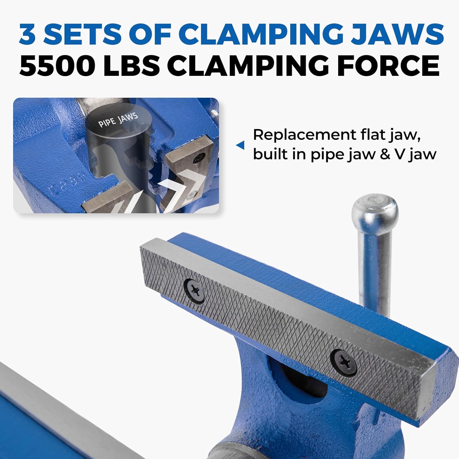
Figure 4: Close-up view of the three types of clamping jaws: replaceable flat jaws, built-in pipe jaws, and V-jaws, highlighting their textured surfaces.
4.4. Integrated Anvil
A large, reinforced anvil (65x48mm / 2.6 x 1.9in) is integrated into the vise, allowing for grinding, cutting, and tapping work directly on the vise.

Figure 5: Detailed diagram showing the key dimensions of the vise, including jaw opening, throat depth, pipe capacity, and anvil size, illustrating the ample workspace.
5. Setup: Mounting Instructions
Proper mounting is essential for the stability and safe operation of your bench vise. The vise is designed for easy and solid lockdown to your workbench.
- Positioning: Choose a sturdy workbench or surface capable of supporting the weight and forces exerted during vise operation. Position the vise so that the fixed jaw extends slightly beyond the edge of the workbench, allowing for vertical clamping of longer workpieces.
- Marking Holes: Place the vise on the desired mounting location. Use a pencil or marker to accurately mark the centers of the four mounting holes on your workbench.
- Drilling Holes: Drill four 1/2-inch (13mm) diameter holes through your workbench at the marked locations. Ensure the holes are straight and clean.
- Securing the Vise: Align the vise's mounting holes with the drilled holes. Insert the provided 1/2-inch (13mm) mounting bolts through the vise base and the workbench. Use flat washers and nuts on the underside of the workbench to secure the bolts.
- Tightening: Hand-tighten the lock handles and mounting bolts initially. Once positioned correctly, fully tighten all mounting bolts to ensure a solid and secure attachment.
Important: Do not weld the vise to any metal object. Secure the vise by hand tightening the lock handles. Do not use a pipe extension or cheater bar on the leadscrew handle of the vise.
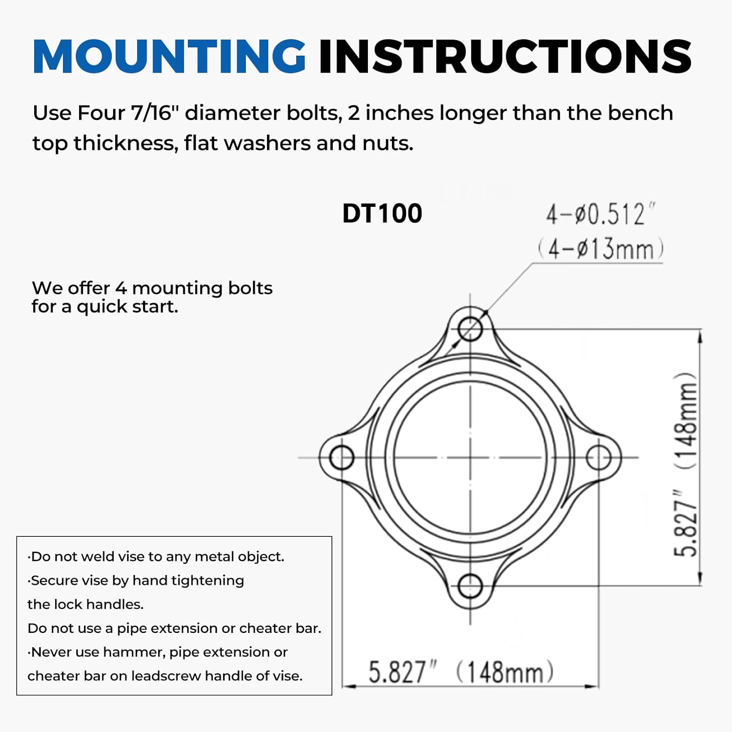
Figure 6: Technical drawing illustrating the mounting hole dimensions and layout for the DT100 model, along with key safety warnings for installation.
6. Operating Instructions
Operating your Forward bench vise is straightforward. Follow these steps for effective use:
- Clamping a Workpiece:
- Turn the main handle counter-clockwise to open the jaws to a width slightly larger than your workpiece.
- Place the workpiece firmly between the jaws.
- Turn the main handle clockwise to close the jaws until the workpiece is securely clamped. Ensure the workpiece is stable and does not wobble.
- Using the Pipe Jaws: For cylindrical objects, position the item in the built-in pipe jaws located below the main jaws. Tighten the main handle to secure the pipe.
- Utilizing the Anvil: The flat, reinforced surface on the rear of the fixed jaw serves as an anvil. Use it for light hammering, shaping, or other tasks that require a solid striking surface.
- Rotating the Vise Head: To rotate the vise head, loosen the position locking screw on the side of the head. Rotate the head to the desired angle, then re-tighten the locking screw firmly.
- Rotating the Swivel Base: To rotate the entire vise on its base, loosen the two locking screws on the sides of the swivel base. Rotate the vise to the desired position (up to 360 degrees), then re-tighten both locking screws securely to prevent movement during work.
7. Maintenance
Regular maintenance will ensure your Forward bench vise remains in optimal working condition for years to come.
- Cleaning: After each use, wipe down the vise to remove any dust, debris, or metal shavings. A stiff brush can be used for textured areas.
- Lubrication: Periodically apply a light coat of machine oil or grease to the main screw mechanism and sliding surfaces. This ensures smooth operation and prevents rust.
- Jaw Inspection: Check the jaws for wear or damage. The top jaws are replaceable if they become excessively worn.
- Bolt Tightness: Regularly check the tightness of the mounting bolts and the swivel base locking screws. Re-tighten as necessary to maintain stability.
- Storage: When not in use, keep the vise jaws slightly open to prevent rust and maintain proper alignment. Store the vise in a dry environment.
8. Troubleshooting
Here are some common issues and their potential solutions:
- Jaws not clamping securely:
- Ensure the workpiece is properly seated and the main handle is fully tightened.
- Check if the jaws are worn or damaged and require replacement.
- Vise movement during use:
- Verify that all four mounting bolts are securely tightened to the workbench.
- Ensure the swivel base locking screws are fully tightened.
- Stiff or difficult operation of the main screw:
- Apply lubrication to the main screw and sliding surfaces as described in the Maintenance section.
- Check for any debris or obstructions in the screw mechanism.
- Jaws chipping:
- Avoid clamping hardened materials that exceed the vise's capacity.
- Ensure proper workpiece alignment to distribute clamping force evenly.
9. Specifications
Detailed technical specifications for the Forward HY-DT100-4IN Bench Vise:
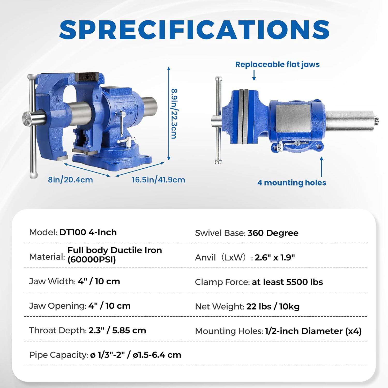
Figure 7: A visual representation of the key specifications of the DT100 4-inch model, including dimensions and material properties.
| Attribute | Detail |
|---|---|
| Model | HY-DT100-4In (DT100 4-Inch) |
| Material (Floating Body & Swivel Base) | Ductile Iron (60,000 PSI) |
| Material (Stationary Body) | Gray Iron (30,000 PSI) |
| Jaw Width | 100mm (4 inches / 10 cm) |
| Jaw Opening | 100mm (4 inches / 10 cm) |
| Throat Depth | 58.5mm (2.3 inches / 5.85 cm) |
| Clamp Force | At least 5,500 lbs (25 k.N) |
| Anvil Size (L x W) | 65x48mm (2.6 x 1.9 inches) |
| Pipe Capacity | φ 1/3" - 2" (φ1.5 - 6.4 cm) |
| Swivel Base | 360 Degree Rotation |
| Item Dimensions (L x W x H) | 13.8 x 6.3 x 7.4 inches |
| Net Weight | 10.5 Kilograms (23.1 lbs) |
| Color | Blue |
| Finish | Coated |
10. Warranty and Support
Forward is committed to providing high-quality products and excellent customer service.
- 30-Day Return Policy: Enjoy a 30-day no-questions-asked return period from the date of purchase.
- 1-Year Limited Parts Replacement: Your Forward HY-DT100-4IN Bench Vise is covered by a 1-year limited warranty for parts replacement, covering manufacturing defects and material flaws under normal use.
- Lifetime Technical Support Guarantee: Forward offers lifetime technical support for your product.
- 24/7 Email Customer Support: For any inquiries, technical assistance, or warranty claims, please contact our customer support team via email.

Figure 8: Visual summary of Forward's warranty and support offerings, including 30-day return, 1-year parts replacement, lifetime technical support, and 24/7 email support.