1. Product Overview
The Cuifati ITX Computer Motherboard H6 ME is designed for compact computing systems, offering essential features for a reliable and efficient build. This motherboard supports LGA 1155 CPUs and DDR3 memory, providing a stable foundation for various applications.
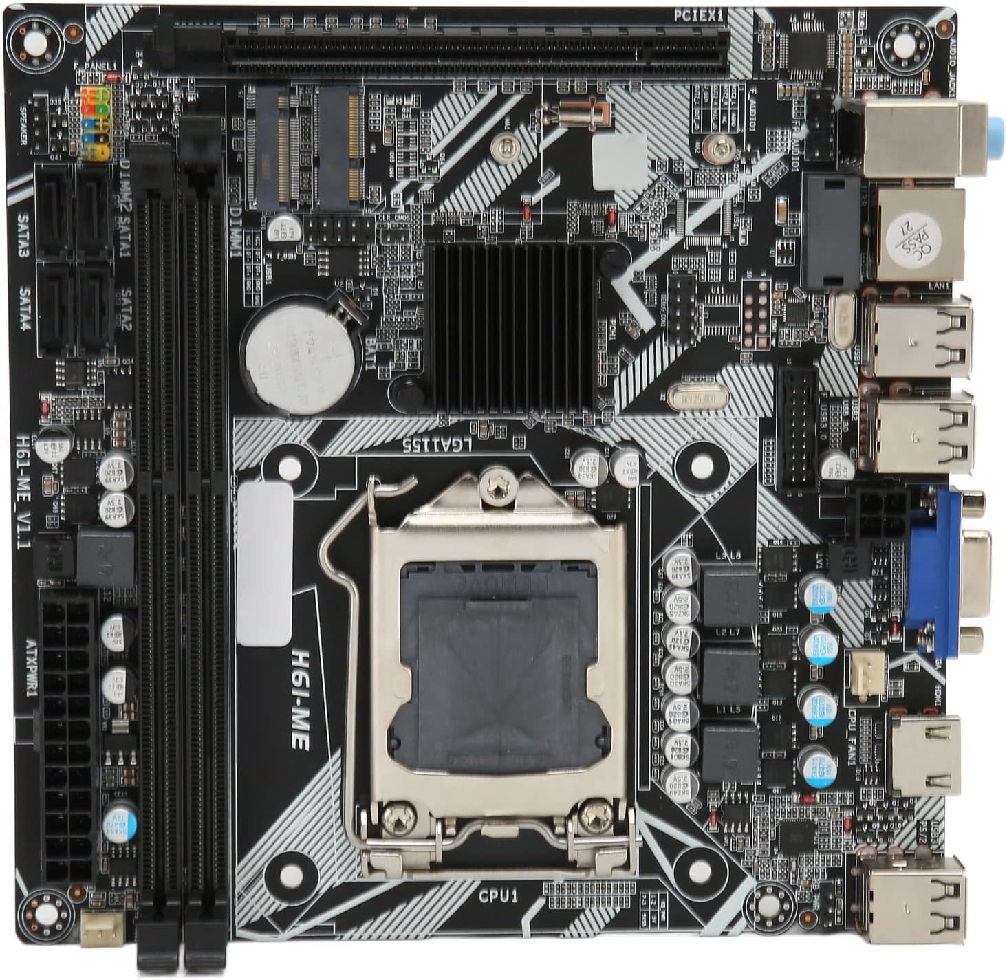
Figure 1: Cuifati ITX Computer Motherboard H6 ME (Top View)
2. Key Features
- LGA 1155 CPU Slot: Supports LGA 1155 processors for stable performance.
- Multiphase Power Design: Features stable and accurate multiphase power delivery for improved CPU performance.
- HD Video Output: Equipped with VGA and HD Multimedia Interface (HDMI) for digital high-definition video output.
- Dual Channel DDR3 Memory: Incorporates two DDR3 memory slots, supporting up to 16GB, enhancing overall system performance.
- Multiple USB2.0 Interfaces: Provides 10 USB2.0 interfaces (4 front, 6 rear) for extensive peripheral connectivity.
- Storage Options: Includes 4 SATA2.0 ports and M.2 NVME support for various storage solutions.
- PCIe 16X Slot: Features a PCIe 16X slot for dedicated graphics cards or other expansion cards.
3. Package Contents
Verify that all items are present in the package before proceeding with installation.
- 1 x Cuifati LGA 1155 Motherboard (H6 ME)
- 1 x Metal I/O Plate
- 1 x SATA Connecting Cable

Figure 2: Motherboard and Included Accessories
4. Setup and Installation
This section provides instructions for installing the Cuifati H6 ME motherboard into your computer system. Ensure your system is powered off and unplugged before beginning any installation.
4.1. Component Identification
Familiarize yourself with the layout of the motherboard and its various connectors.

Figure 3: Motherboard Component Diagram
- CPU Slot (LGA 1155): For installing your Intel LGA 1155 processor.
- DDR3 Slots: Two slots for DDR3 memory modules.
- PCIe 16X Slot: For graphics cards or other expansion cards.
- SATA2.0 Ports: Four ports for connecting SATA storage devices (HDDs/SSDs).
- NVME M.2 Slot: For high-speed NVME M.2 SSDs.
- Front Panel Connectors: Pins for power switch, reset switch, HDD LED, and power LED.
- USB2.0 Headers: For front panel USB ports.
- 24-Pin ATX Power Connector: Main power input from the power supply.
- 4-Pin CPU Power Connector: Additional power for the CPU.
- Rear I/O Ports: USB, VGA, HDMI, LAN, Audio ports.
4.2. Installation Steps
- Prepare the Case: Ensure your computer case is ready for motherboard installation. Install standoffs if necessary.
- Install the I/O Shield: Snap the metal I/O plate into the corresponding opening in your computer case.
- Install the CPU:
- Open the CPU socket lever and remove the protective cover.
- Carefully align your LGA 1155 CPU with the socket, ensuring the notches on the CPU match the keys on the socket.
- Gently place the CPU into the socket. Do not force it.
- Close the socket lever to secure the CPU.
- Install the CPU Cooler: Apply thermal paste (if not pre-applied) and install your CPU cooler according to its manufacturer's instructions. Connect the CPU fan cable to the "CPU FAN" header on the motherboard.
- Install Memory (RAM):
- Open the clips on both ends of the DDR3 memory slots.
- Align the notch on the DDR3 memory module with the key in the slot.
- Press down firmly on both ends of the memory module until the clips snap into place.
- Mount the Motherboard: Carefully place the motherboard into the case, aligning the screw holes with the standoffs. Secure the motherboard with screws.
- Connect Power Supply Cables:
- Connect the 24-pin ATX power cable from your power supply to the main power connector on the motherboard.
- Connect the 4-pin CPU power cable to the CPU power connector.
- Install Storage Devices: Connect your SATA HDDs/SSDs to the SATA2.0 ports using the provided SATA cable. If using an NVME M.2 SSD, install it into the M.2 slot and secure it with the screw.
- Install Graphics Card (Optional): If using a dedicated graphics card, insert it into the PCIe 16X slot and secure it. Connect any necessary PCIe power cables from your power supply.
- Connect Front Panel Cables: Connect the power switch, reset switch, HDD LED, and power LED cables from your case to the corresponding pins on the motherboard's front panel header. Refer to the motherboard diagram (Figure 3) for pin assignments.
- Connect USB and Audio Cables: Connect front panel USB and audio cables to their respective headers on the motherboard.

Figure 4: PCIe 16X Slot for Expansion Cards
5. Operating Instructions
Once all components are installed and connected, you can power on your system.
5.1. Initial Power On
- Connect your monitor, keyboard, and mouse to the appropriate ports on the rear I/O panel.
- Plug in the power cable to your power supply and turn on the power supply switch.
- Press the power button on your computer case.
- The system should boot up, and you should see output on your monitor.
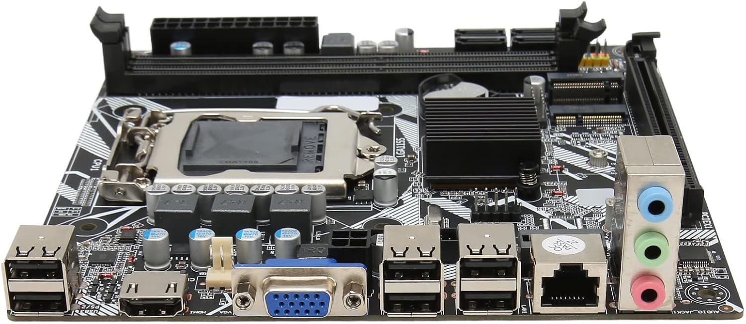
Figure 5: Rear I/O Ports
5.2. BIOS/UEFI Setup
To access the BIOS/UEFI setup utility, press the designated key (usually DEL or F2) repeatedly during the initial boot sequence. From the BIOS, you can configure system settings, boot order, and monitor hardware status.
5.3. Operating System Installation
Once the system is stable, you can proceed with installing your preferred operating system (e.g., Windows, Linux) from a bootable USB drive or DVD.
6. Maintenance
Proper maintenance can extend the lifespan of your motherboard and ensure optimal performance.
- Dust Removal: Regularly clean dust from inside your computer case, especially from fans and heatsinks, using compressed air. Ensure the system is powered off and unplugged before cleaning.
- Cable Management: Ensure cables are neatly routed to improve airflow and prevent interference.
- BIOS Updates: Periodically check the manufacturer's website for BIOS updates. Update the BIOS only if necessary and follow the instructions carefully to avoid system instability.
- Environmental Conditions: Operate the motherboard in a well-ventilated area, away from direct sunlight, excessive heat, and moisture.
7. Troubleshooting
This section addresses common issues you might encounter.
- No Power:
- Check if the power supply is plugged in and switched on.
- Verify that the 24-pin and 4-pin power cables are securely connected to the motherboard.
- Ensure the front panel power switch cable is correctly connected to the motherboard header.
- No Display:
- Confirm that the monitor is connected to the correct video output (VGA or HDMI) on the motherboard or graphics card.
- Reseat the RAM modules. Try booting with only one RAM module installed.
- Reseat the graphics card (if applicable).
- Ensure the CPU is properly seated and the CPU cooler is installed correctly.
- System Instability/Crashes:
- Check for overheating. Ensure CPU cooler and case fans are functioning.
- Test memory modules for errors using diagnostic tools.
- Ensure all drivers (chipset, graphics, etc.) are up to date.
- Peripheral Not Detected:
- Try connecting the peripheral to a different USB port.
- Ensure necessary drivers are installed for the peripheral.
- Check BIOS settings to ensure USB ports are enabled.
8. Specifications
| Feature | Description |
|---|---|
| Motherboard Model | H6 ME |
| Motherboard Type | ITX |
| CPU Slot Type | LGA 1155 |
| Memory Slots | DDR3 x 2 |
| Max Memory Capacity | Up to 16GB |
| SATA Ports | SATA2.0 x 4 |
| Graphics Card Slot | PCIe 16X |
| USB Interfaces | USB2.0 x 10 (4 Front, 6 Rear) |
| Expansion Interfaces | VGA x 1, HD Multimedia Interface (HDMI) x 1, M.2, NVME M.2, DEBUG Pin x 1 |
| Sound Audio Card | Realtek ALC662 Sound Chip |
| Network Card | 100M Network Card |
| Inbuilt Battery | 240mAh CR2032 x 1 |
| Item Weight | 1.13 pounds |
| Package Dimensions | 8.27 x 7.87 x 1.97 inches |
| Model Number | CUIFATI6wgctin4bz |
9. Warranty and Support
For warranty information or technical support, please refer to the retailer where the product was purchased or visit the official Cuifati website. Keep your proof of purchase for warranty claims.
Manufacturer: CUIFATI
Date First Available: December 19, 2023
For additional assistance, you may contact Cuifati customer service through their official channels.