LeTkingok T-WY-XH100
Automobile Signal Simulator Tester
Model: WY-XH100
User Manual
Introduction
The LeTkingok WY-XH100 Automobile Signal Simulator Tester is a versatile diagnostic tool designed for automotive professionals and enthusiasts. It allows for the simulation of various sensor signals and resistance values, aiding in the rapid identification and troubleshooting of vehicle electrical system issues. This manual provides detailed instructions for the proper use and maintenance of your device.
Key Features
- Simulates adjustable resistance for various automotive components.
- Equipped with a try light signal function for quick checks.
- Capable of simulating signals for temperature sensors (water, fuel, liquid), liquid level sensors, and exhaust temperature sensors.
- Supports simulation of inlet pressure and temperature sensors.
- Facilitates rapid determination of injector pulse signals and crankshaft position sensor signals for efficient troubleshooting.
What's in the Box
- 1 x Automobile Signal Simulator Tester (Model WY-XH100)
- Necessary connecting cables (as shown in product images)

Image: The WY-XH100 Automobile Signal Simulator Tester, showing the main unit and the included connecting cables with banana plugs and alligator clips.
Setup
- Unpacking: Carefully remove the Automobile Signal Simulator Tester and all accessories from its packaging. Inspect for any signs of damage.
- Familiarization: Identify the various knobs, ports, and indicators on the device. The large black knob controls the main simulation function, while the smaller gold knobs adjust specific resistance values. The red, yellow, and black ports are for connecting the included cables.
- Cable Connection: Connect the provided test leads to the appropriate ports on the simulator and to the vehicle's sensor or ECU as required for the specific test. Ensure secure connections to prevent inaccurate readings or damage.
- Power: The device is typically powered by the vehicle's electrical system or an external power source (not explicitly mentioned, assuming it's self-powered or uses vehicle power). Ensure the vehicle's ignition is off before connecting.

Image: An angled view of the WY-XH100 simulator, highlighting the connection ports and the included test leads.
Operating Instructions
The WY-XH100 is designed to simulate various automotive sensor signals. Below are general guidelines for its operation. Always refer to the vehicle's service manual for specific sensor specifications and testing procedures.
1. Simulating Adjustable Resistance:
- Connect the simulator to the circuit where resistance needs to be tested or simulated.
- Use the gold rotary knobs to adjust the resistance values. The labels (e.g., 1K, 10K, 100K, 1M) indicate the range or multiplier for each knob.
- Observe the vehicle's ECU or diagnostic tool for changes in readings as you adjust the resistance.

Image: A top-down view of the WY-XH100, clearly showing the main rotary knob, the four smaller gold resistance adjustment knobs, and the input/output ports.
2. Simulating Temperature and Liquid Level Sensors:
- The device can simulate signals for water temperature, fuel temperature, liquid temperature, and liquid level sensors.
- Connect the simulator to the sensor's input on the ECU.
- Adjust the appropriate controls (likely the resistance knobs) to mimic different temperature or level readings.
- Monitor the ECU's response to verify sensor functionality or diagnose issues.
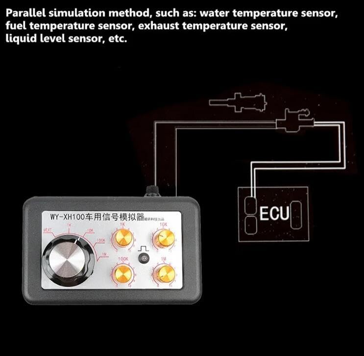
Image: A diagram illustrating the parallel simulation method for sensors such as water temperature, fuel temperature, exhaust temperature, and liquid level sensors, showing connection to an ECU.
3. Simulating Pressure Sensors:
- The WY-XH100 can simulate analog pressure sensors, including rail pressure and inlet pressure sensors.
- Connect the simulator to the pressure sensor's input on the ECU.
- Adjust the simulator's controls to generate varying pressure signals.
- Use a diagnostic scanner to observe the ECU's interpretation of the simulated pressure.
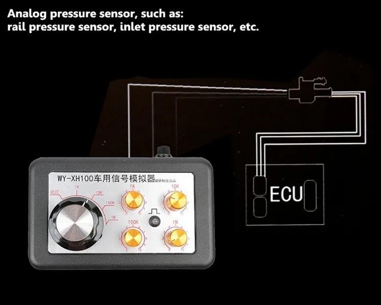
Image: A diagram demonstrating the simulation of analog pressure sensors like rail pressure and inlet pressure sensors, showing the connection to an ECU.
4. Injector Pulse and Crankshaft Position Sensor Signal Testing:
- The "try light" function can quickly determine injector pulse signals. Connect the light output to the injector circuit.
- For crankshaft position sensor signals, connect the simulator to the appropriate input on the ECU. The device can generate signals to test the ECU's response to various RPMs or sensor conditions.
- This feature is crucial for diagnosing engine timing and fuel delivery issues.
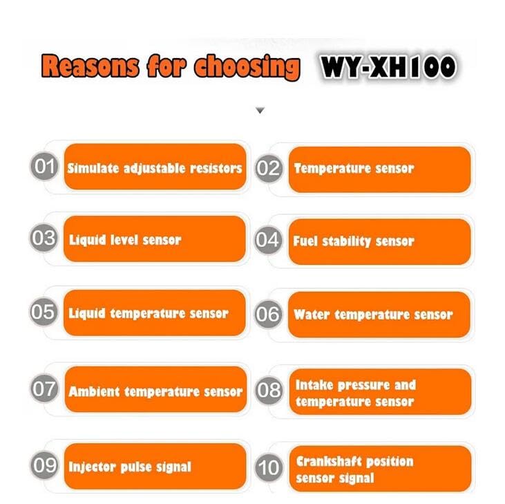
Image: A graphic highlighting the capabilities of the WY-XH100, including simulating adjustable resistors, various temperature sensors, liquid level sensors, intake pressure sensors, injector pulse signals, and crankshaft position sensor signals.
Maintenance
- Cleaning: Wipe the device with a soft, dry cloth. Do not use abrasive cleaners or solvents.
- Storage: Store the simulator in a cool, dry place away from direct sunlight and extreme temperatures. Keep it in its original packaging or a protective case when not in use.
- Cable Care: Inspect connecting cables regularly for fraying or damage. Replace damaged cables immediately to ensure accurate readings and safety.
- Fuse Replacement: The device may contain a fuse (visible on some images). If the device stops functioning, check and replace the fuse with one of the same rating if necessary.
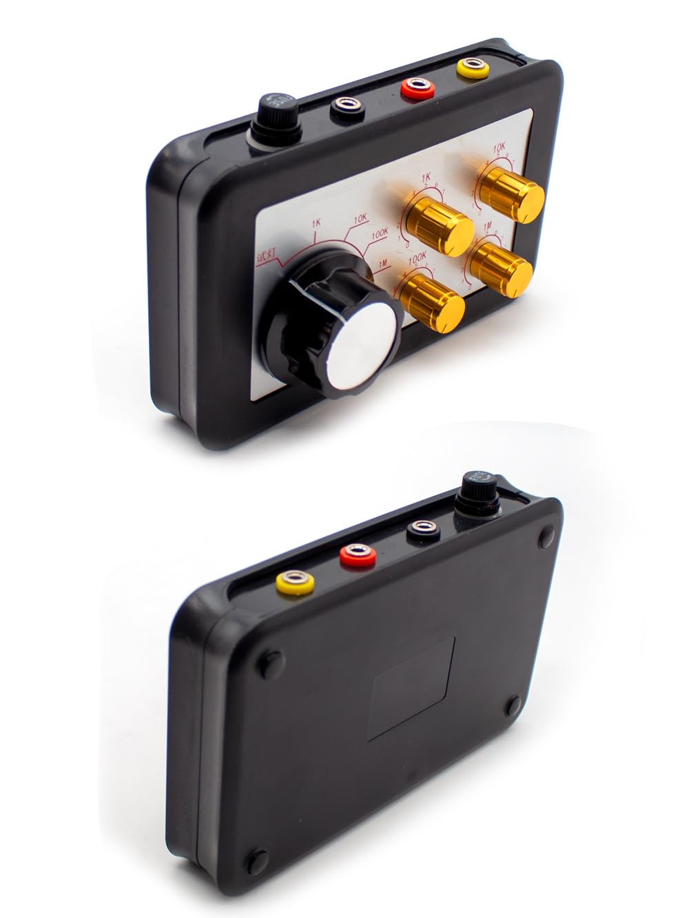
Image: Two perspectives of the WY-XH100 unit, showing the top panel with controls and the plain bottom panel, useful for understanding its physical form for storage and handling.
Troubleshooting
| Problem | Possible Cause | Solution |
|---|---|---|
| Device does not power on. | No power supply; Blown fuse; Loose connection. | Ensure proper connection to vehicle power or external source. Check and replace fuse if necessary. Verify all cable connections are secure. |
| Inaccurate readings/simulation. | Incorrect connection; Damaged cables; Incorrect settings on simulator. | Double-check wiring according to vehicle's service manual. Inspect cables for damage. Ensure knobs are set to the desired simulation values. |
| Try light not illuminating. | No signal present; Incorrect connection; Faulty light. | Verify the circuit being tested is active. Ensure proper connection to the signal source. If all else fails, the light itself may be faulty. |
Specifications
| Attribute | Detail |
|---|---|
| Model Number | T-WY-XH100 |
| Manufacturer | LeTkingok |
| Functionality | Adjustable resistance simulation, temperature sensor simulation (water, fuel, liquid), liquid level sensor simulation, inlet pressure/temperature sensor simulation, injector pulse signal determination, crankshaft position sensor signal simulation. |
| Connectivity | Banana plug ports for test leads. |
Warranty and Support
For warranty information and technical support, please refer to the documentation provided at the time of purchase or contact LeTkingok customer service. Keep your purchase receipt as proof of purchase for any warranty claims.
For further assistance, please visit the official LeTkingok website or contact their support channels.
Ask a question about this manual
Ask about setup, troubleshooting, compatibility, parts, safety, or missing instructions. Manuals+ will review the question and use this page’s manual context to help answer it.