1. Introduction
This manual provides essential information for the safe and efficient operation of the JOCCOS Hybrid AC Servo Driver, specifically the A1-SVD20 model and related variants. It covers product features, installation, operation, maintenance, and troubleshooting to ensure optimal performance and longevity of your servo system.
The JOCCOS Hybrid AC Servo Driver series is designed for stable performance and fast response in various industrial applications. Key features include advanced heat dissipation and, for most models, an integrated cooling fan.
2. Safety Information
Always observe the following safety precautions to prevent personal injury or damage to the equipment:
- Ensure the power supply is disconnected before performing any installation, wiring, or maintenance.
- Only qualified personnel should install, operate, and maintain this device.
- Verify correct wiring connections according to the diagrams provided in this manual. Incorrect wiring can lead to malfunction or damage.
- Do not operate the driver in environments with excessive moisture, dust, corrosive gases, or flammable materials.
- Ensure proper grounding of the device.
- Avoid touching internal components while the device is powered on or immediately after power-off, as residual voltage may be present.
3. Product Overview
3.1 Driver Components
The Hybrid AC Servo Driver features a compact design with essential interfaces and a digital display for status and parameter settings.
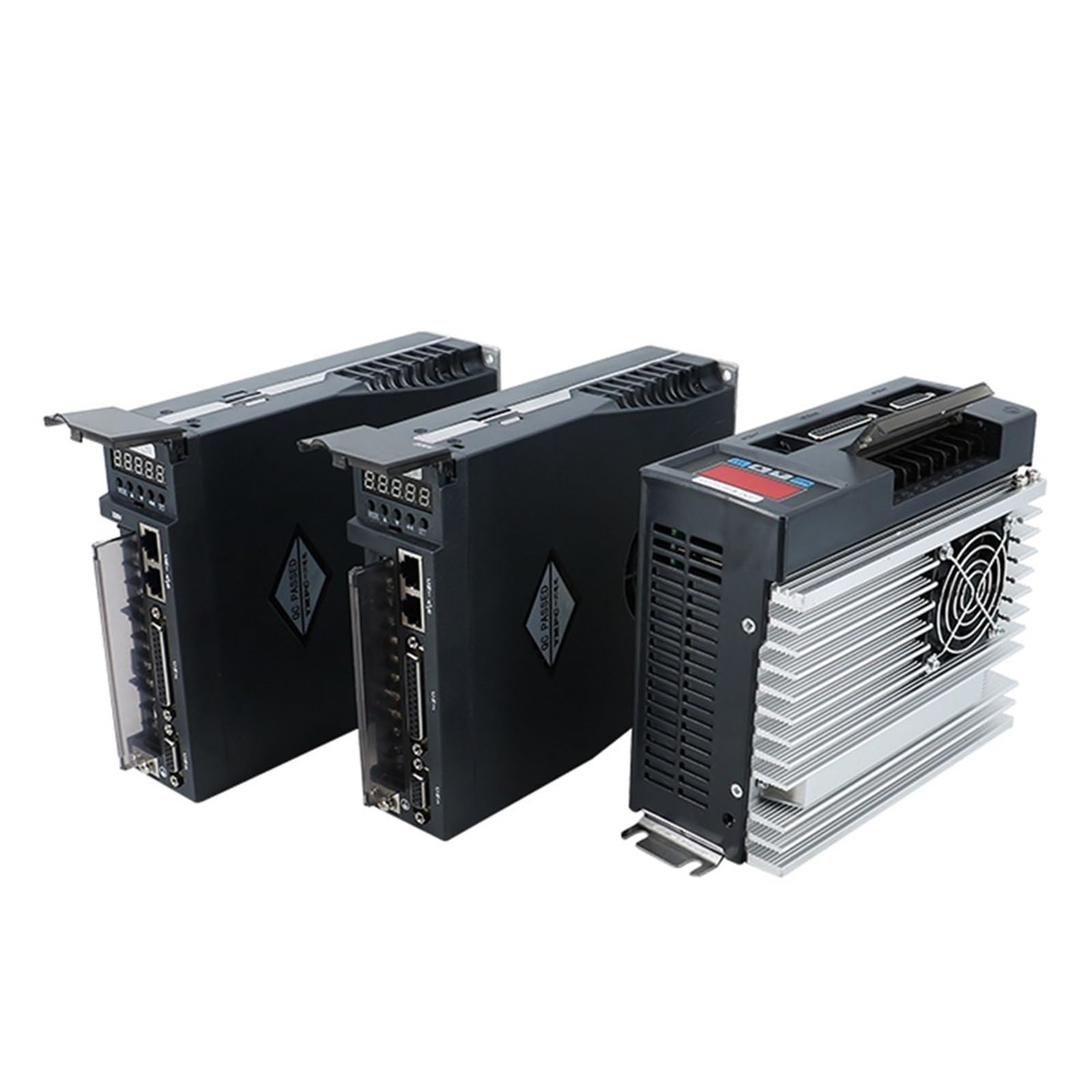
Figure 1: Front view of a JOCCOS A1-SVD series Hybrid AC Servo Driver, illustrating the digital display, control buttons, and various communication and power connection ports.
3.2 Communication and Power Interfaces
The driver includes several interfaces for control and power:
- PC Signal Input: For connecting to a computer for configuration and monitoring.
- Encoder Signal Input: For receiving feedback from the servo motor's encoder.
- Control Circuit Power Supply: Dedicated power input for the driver's control logic.
- Main Circuit Power Supply: High-voltage power input for the motor drive.
- External Braking Resistor Interface: For connecting an optional external braking resistor.
- Motor Power Line: Output terminals for connecting to the servo motor.
- Ground Terminal: Essential for safety and proper operation.
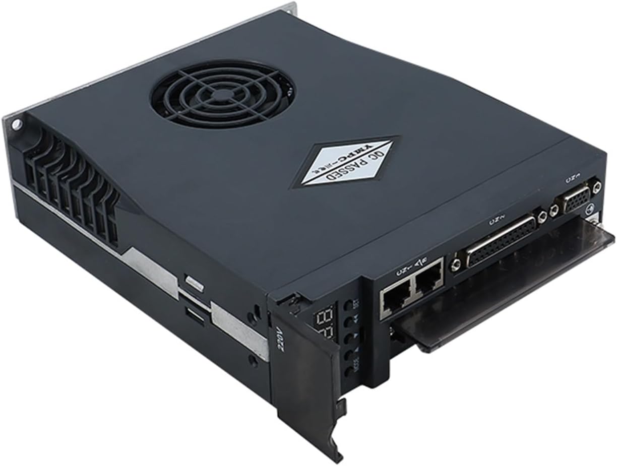
Figure 2: Top-down view of the servo driver, highlighting the arrangement of communication ports (e.g., Ethernet-style, D-sub) and power terminals.
3.3 Control Buttons and Display
The driver features a digital display and several buttons for local control and parameter adjustment:
- MODE Key: Used for mode switching and navigating to the upper-level menu directly.
- Increase Key (▲): Increases numerical values. Long press provides a repeating effect.
- Decrease Key (▼): Decreases numerical values. Long press provides a repeating effect.
- SHIFT Key: Shifts the cursor position during parameter entry.
- SET (OK) Key: Confirms settings and ends parameter adjustments.
4. Setup and Installation
Proper installation is crucial for the driver's performance and safety. Follow these guidelines:
4.1 Mounting
Mount the driver in a vertical position to facilitate natural convection cooling. Ensure adequate clearance around the unit for airflow, especially for models with cooling fans.

Figure 3: Rear view of the servo driver, illustrating the heat sink fins and integrated cooling fan (present on most models).
4.2 Wiring Connections
Connect the servo driver to the power supply, servo motor, and control system according to the specific wiring diagrams provided with your product. Ensure all connections are secure and correctly polarized.
- Power Supply: Connect the main circuit power supply (typically 220V AC) and the control circuit power supply to their respective terminals.
- Motor Connection: Connect the motor power lines (U, V, W) and the motor's encoder feedback cable to the designated terminals.
- Grounding: Connect the ground terminal to a reliable earth ground.
- Control Signals: Connect PC signal input and other control signals as required by your application.
5. Operating Instructions
After successful installation and wiring, the driver is ready for operation. Refer to the specific programming guide for detailed parameter settings.
5.1 Powering On
Apply power to the control circuit first, then to the main circuit. The digital display will illuminate, indicating the driver's status.
5.2 Parameter Setting
Use the MODE, Increase, Decrease, SHIFT, and SET keys to navigate through menus and adjust operational parameters. Consult the detailed parameter list in the full technical manual for specific functions.
5.3 Alarm Indication
Note: If all 5 decimal points of the display screen are flashing, it indicates that an alarm has been generated. The alarm must be cleared before the driver can operate normally. Refer to the Troubleshooting section for alarm codes and resolution steps.
6. Maintenance
Regular maintenance ensures the longevity and reliable operation of your servo driver.
- Cleaning: Periodically clean the driver's exterior, especially the heat sink and cooling fan (if present), to prevent dust accumulation that can hinder heat dissipation. Use a soft, dry cloth.
- Cooling Fan: The A1-SVD20 model includes a cooling fan for advanced heat dissipation. Ensure the fan is free from obstructions and operating correctly. Note that the 15A driver models (e.g., A1-SVD15, AASD-15A) typically do not include a cooling fan.
- Connections: Periodically check all wiring connections for tightness and signs of wear or corrosion.
- Environment: Maintain a clean, dry, and well-ventilated operating environment within the specified temperature and humidity ranges.
7. Troubleshooting
This section provides guidance for common issues and alarm conditions.
7.1 Alarm Conditions
As noted, if all 5 decimal points on the display screen are flashing, an alarm has occurred. The specific alarm code will typically be displayed. To resolve an alarm:
- Identify the alarm code displayed on the driver.
- Refer to the comprehensive alarm code list in the full technical manual for the cause and recommended corrective actions.
- Address the root cause of the alarm (e.g., overcurrent, overvoltage, encoder error).
- Clear the alarm using the appropriate method (often by cycling power or a specific button sequence) once the issue is resolved. The driver will not operate until the alarm is cleared.
7.2 Common Issues
- No Power: Check power supply connections, fuses, and circuit breakers.
- Motor Not Moving: Verify motor wiring, encoder connections, and control signal inputs. Check for any active alarms.
- Erratic Operation: Inspect for electrical noise, loose connections, or incorrect parameter settings.
8. Specifications
The following table outlines the general specifications for the JOCCOS Hybrid AC Servo Driver series, including the A1-SVD and AASD models:
| Model | Current (A) | Voltage (V) | Application For Servo Motor |
|---|---|---|---|
| AASD-15A | 15A | 220V | 0.4-0.75KW |
| AASD-20A | 20A | 220V | 1KW |
| AASD-30A | 30A | 220V | 1.2-2.6KW |
| AASD-50A | 50A | 220V | 3.5KW |
| A1-SVD15 | 15A | 220V | 0.4-0.75KW |
| A1-SVD20 | 20A | 220V | 1KW |
| A1-SVD30 | 30A | 220V | 1.2-2.6KW |
Brand: JOCCOS
Item Weight: Approximately 50 Grams (Note: This weight may refer to a specific component or packaging, actual unit weight may vary.)
9. Warranty and Support
For warranty information, technical support, or service inquiries, please contact your vendor or the manufacturer directly. Keep your purchase receipt and product serial number handy for faster assistance.
An English manual may be available for download via this link: JOCCOS Servo Driver English Manual