
1. Product Overview
The JOCCOS A1-SVD / AASD series hybrid AC servo driver is designed for precise motor control applications. This series offers stable performance and fast response times, making it suitable for various industrial and automation tasks. Key features include an advanced heat dissipation design to ensure reliable operation.
This manual covers models such as A1-SVD15, A1-SVD20, A1-SVD30, AASD-15A, AASD-20A, AASD-30A, and AASD-50A.

Figure 1: Various JOCCOS A1-SVD / AASD Series Hybrid AC Servo Drivers.
2. Product Components and Interfaces
The servo driver features several interfaces for connectivity and control. Understanding these interfaces is crucial for proper installation and operation.
- Communication Interface: For data exchange with external devices.
- PC Signal Input: Connects to a personal computer for configuration and monitoring.
- Encoder Signal Input: Receives feedback from the motor's encoder for precise positioning.
- Control Circuit Power Supply: Provides power to the internal control electronics.
- Main Circuit Power Supply: Supplies power to the motor drive section.
- External Braking Resistor Interface: For connecting an optional external braking resistor.
- Motor Power Cable: Connects the driver to the servo motor.
- Ground Terminal: Essential for safety and proper operation.
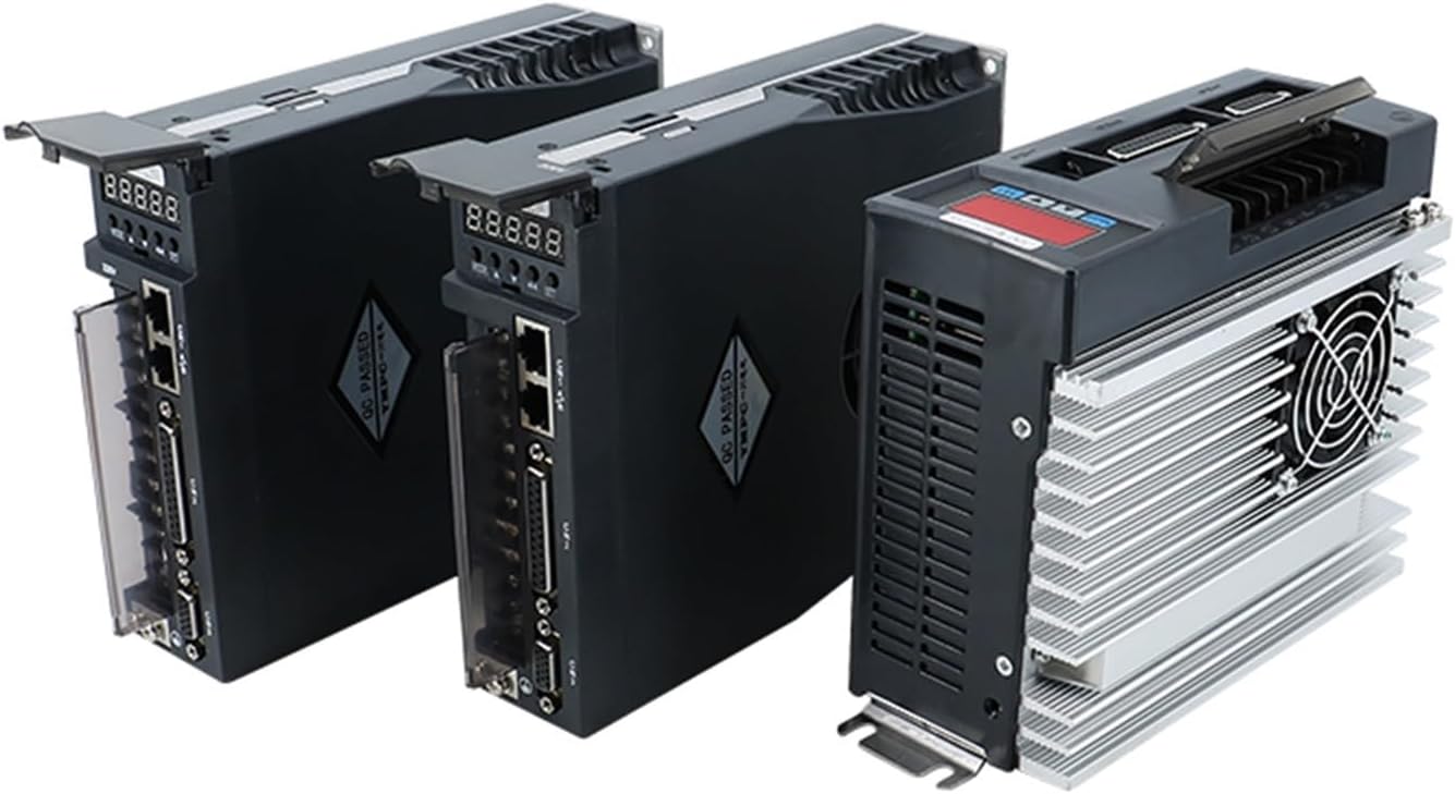
Figure 2: Connection terminals on the servo driver.
3. Control Panel and Buttons
The front panel of the servo driver features a display and several buttons for configuration and status monitoring.
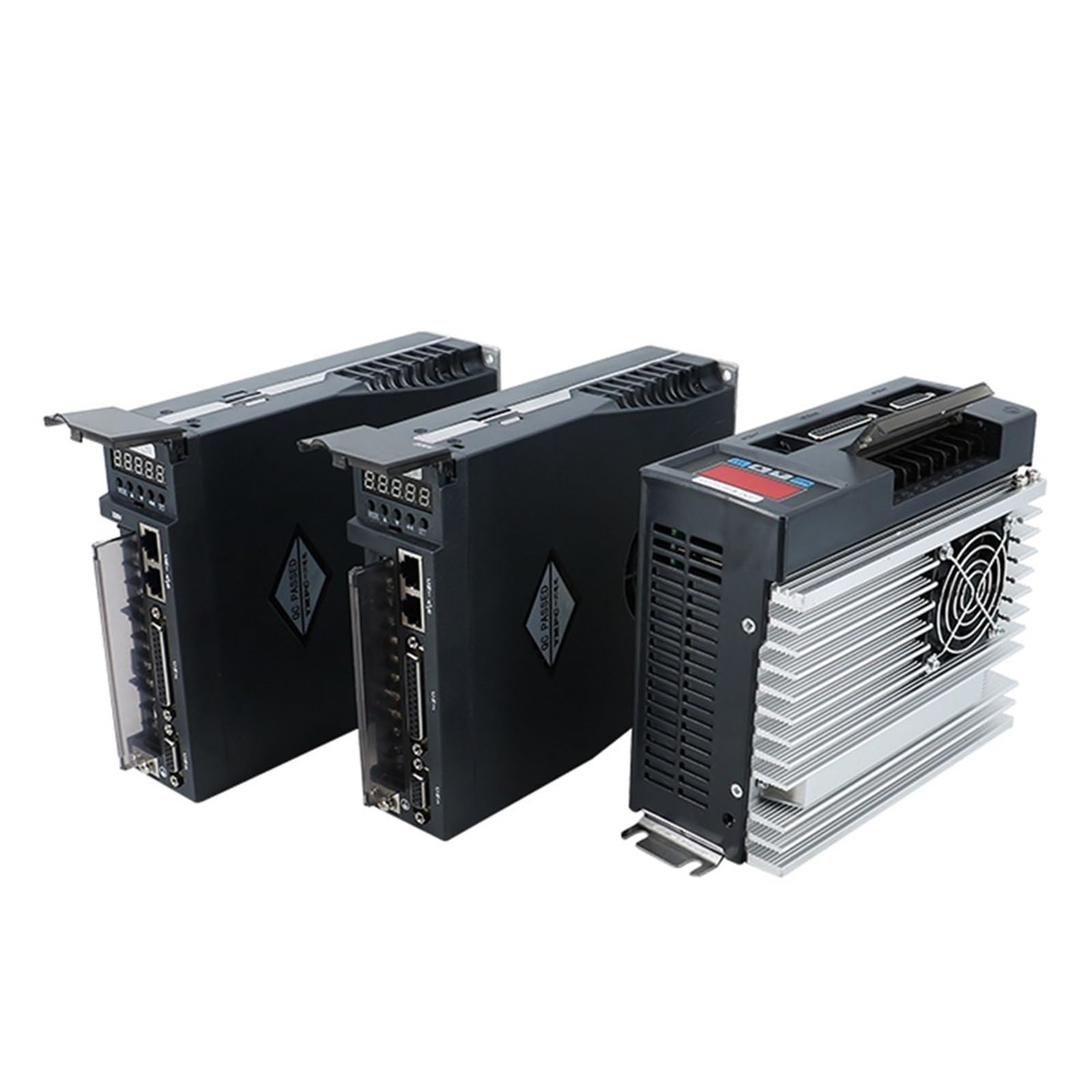
Figure 3: Front panel with display and control buttons.
Button Functions:
- MODE Button:
- Switches between different operating modes.
- Returns to the previous menu level.
- UP Button (▲):
- Increases numerical values.
- Press and hold for continuous increment.
- DOWN Button (▼):
- Decreases numerical values.
- Press and hold for continuous decrement.
- SHIFT Button (←):
- Shifts the cursor position on the display.
- OK Button (SET):
- Confirms parameter settings.
- Finalizes parameter adjustments.
4. Setup and Installation
Proper setup is essential for the safe and efficient operation of the servo driver.
- Mounting: Mount the servo driver in a location with adequate ventilation to ensure optimal heat dissipation.
- Power Connections:
- Connect the Main Circuit Power Supply and Control Circuit Power Supply according to the specifications.
- Ensure proper grounding by connecting to the Ground Terminal.
- Motor Connection: Connect the servo motor to the Motor Power Cable interface.
- Encoder Connection: Connect the motor's encoder to the Encoder Signal Input for feedback.
- Communication: If required, connect the PC or other control devices to the Communication Interface and PC Signal Input.
- Braking Resistor: If an external braking resistor is used, connect it to the External Braking Resistor Interface.
Always ensure all connections are secure and correctly polarized before applying power.
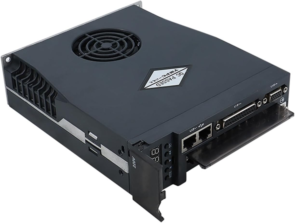
Figure 4: Top-down view illustrating various connection points.
5. Operating Instructions
Once the servo driver is properly installed and powered, follow these steps for basic operation:
- Power On: Apply power to both the control circuit and the main circuit.
- Mode Selection: Use the MODE button to navigate through different operating modes or menu levels.
- Parameter Adjustment: When in a parameter setting mode, use the UP (▲) and DOWN (▼) buttons to adjust numerical values. Use the SHIFT (←) button to move the cursor for digit selection.
- Confirmation: Press the OK (SET) button to confirm any parameter changes or to finalize settings.
- Monitoring: Observe the display for status information and operational feedback.
6. Maintenance
Regular maintenance helps ensure the longevity and optimal performance of your servo driver.
- Heat Dissipation: The driver features an advanced heat dissipation design. Ensure that the cooling fins and fan (present on models other than 15A drivers) are free from dust and obstructions.
- Cleaning: Periodically clean the exterior of the driver with a soft, dry cloth. Do not use liquid cleaners or solvents.
- Ventilation: Ensure adequate airflow around the unit. Do not block ventilation openings.
- Connection Check: Regularly inspect all electrical connections for tightness and signs of wear or corrosion.

Figure 5: Rear view showing the cooling fan and heat sink for effective heat dissipation.
7. Troubleshooting
This section addresses common issues you might encounter during operation.
Alarm Condition:
Symptom: The 5 decimal points on the display are flashing.
Cause: An alarm condition has been triggered.
Resolution: The alarm must be cleared before the driver can operate normally. Refer to the detailed English manual (link provided in Section 9) for specific alarm codes and clearing procedures.
8. Specifications
Below are the general specifications for the JOCCOS A1-SVD / AASD series servo drivers.
| Model | Current | Voltage | Power Range |
|---|---|---|---|
| AASD-15A | 15 A | 220 V | 0.4 to 0.75 kW |
| AASD-20A | 20 A | 220 V | 1 kW |
| AASD-30A | 30 A | 220 V | 1.2 to 2.6 kW |
| AASD-50A | 50 A | 220 V | 3.5 kW |
| A1-SVD15 | 15 A | 220 V | 0.4 to 0.75 kW |
| A1-SVD20 | 20 A | 220 V | 1 kW |
| A1-SVD30 | 30 A | 220 V | 1.2 to 2.6 kW |
General Product Specifications:
- Manufacturer: JOCCOS
- Model Name: JOCCOS (A1-SVD / AASD Series)
- Voltage: 110 Volts (Note: Specific models listed above operate at 220V, refer to model table for details)
- Power: 500 Watts (General rating, specific models vary as per table)
- Item Weight: 50 Grams
- Package Dimensions: 3 x 2 x 1 cm
9. Support and Warranty
For detailed technical support, advanced configurations, or specific troubleshooting guides, please refer to the comprehensive English manual available online.
Official English Manual: Download English Manual
For warranty information or further assistance, please contact your vendor or JOCCOS customer support.


