1. Introduction
This manual provides detailed instructions for the LAFVIN 4.0-inch TFT LCD Touch Display Module. This module features a 480x320 resolution, SPI serial interface, and an ST7796S driver IC, making it suitable for various microcontroller projects, including those based on Arduino. It includes a resistive touch screen for interactive applications and an integrated SD card slot for data storage.
2. Product Features
- Display Size: 4.0 inches
- Resolution: 480 x 320 pixels
- Driver IC: ST7796S
- Interface: SPI Serial (4-wire SPI for display, separate SPI for touch)
- Touch Screen Type: Resistive (XPT2046 controller)
- Power Voltage: 3.3V ~ 5V DC
- Integrated: SD Card Slot
- Compatibility: Designed for use with microcontrollers like Arduino, ESP32, and Raspberry Pi.
3. Package Contents
The package typically includes:
- 1 x LAFVIN 4.0-inch TFT LCD Touch Display Module
- 1 x Stylus Pen

Figure 3.1: Front and back view of the LAFVIN 4.0-inch TFT LCD Touch Display Module, showing the display, PCB, and the included stylus. The back view highlights the SD card slot and pin headers.
4. Specifications
| Feature | Specification |
|---|---|
| Display Size | 4.0 inches |
| Resolution | 480 x 320 pixels |
| Driver IC | ST7796S |
| Touch Screen Controller | XPT2046 |
| Interface | SPI Serial (4-wire) |
| VCC Power Voltage | 3.3V ~ 5V |
| Effective Area | 55.68 x 83.52 mm |
| PCB Floor Size | 61.74 x 108.04 mm |
| Weight | 71g (module only) |
| Color Depth | RGB 65K color |
5. Pinout Description
Understanding the pin assignments is crucial for proper connection and operation of the display module. The module features dedicated pins for LCD control and a separate set for touch screen functionality.

Figure 5.1: Pin Label and Description for the LAFVIN 4.0-inch TFT LCD Touch Display Module. This table details each pin's function, including power, LCD control, and touch screen interface.
| Pin No. | Label | Description |
|---|---|---|
| 1 | VCC | 5V/3.3V power input |
| 2 | GND | Ground |
| 3 | CS | LCD chip select signal, low level enable |
| 4 | RESET | LCD reset signal, low level reset |
| 5 | DC/RS | LCD command / data selection signal, high level: data, low level: command |
| 6 | SDI(MOSI) | LCD SPI bus write data signal |
| 7 | SCK | LCD SPI bus clock signal |
| 8 | LED | Backlight control, high level lighting. If not controlled, connect 3.3V always bright. |
| 9 | SDO(MISO) | LCD SPI bus read data signal. If read function is not needed, this pin can be left unconnected. |
| Touch Screen Signal Line Wiring (Connect only if touch function is required) | ||
| 10 | T_CLK | Touch SPI bus clock signal |
| 11 | T_CS | Touch screen chip select signal, low level enable |
| 12 | T_DIN | Touch SPI bus input |
| 13 | T_DO | Touch SPI bus output |
| 14 | T_IRQ | Touch screen interrupt signal, low level when touch is detected |
6. Setup and Connection
This section guides you through connecting the display module to your microcontroller board, such as an Arduino or ESP32.
6.1. Wiring the Display Module
The display uses a Serial Peripheral Interface (SPI) for communication. Ensure your microcontroller supports SPI and has available pins for connection.
- Power Connection: Connect the VCC pin to your microcontroller's 3.3V or 5V power supply and GND to ground. The module supports both voltages.
- LCD SPI Connection: Connect the LCD's CS, DC/RS, SDI (MOSI), SCK, and SDO (MISO) pins to the corresponding SPI pins on your microcontroller. Refer to your microcontroller's datasheet for specific SPI pin assignments.
- Reset Pin: Connect the RESET pin to a digital pin on your microcontroller.
- Backlight Control: The LED pin controls the backlight. For constant brightness, connect it to 3.3V. For software control, connect it to a PWM-capable digital pin.
- Touch Screen SPI Connection (Optional): If using the touch function, connect the touch screen's T_CS, T_DIN, T_DO, T_CLK, and T_IRQ pins to separate digital pins on your microcontroller. Note that the touch screen often uses a separate SPI interface or different CS pin from the display.
6.2. Software Setup and Libraries
To control the display and touch screen, you will need appropriate libraries for your development environment (e.g., Arduino IDE).
- Display Library: For Arduino, libraries like TFT_eSPI by Bodmer are commonly used for ST7796S drivers. Configure the `User_Setup.h` file within the library to match your specific display driver (ST7796_DRIVER) and pin connections.
- Touch Screen Library: For the XPT2046 touch controller, libraries such as XPT2046_Touchscreen by Paul Stoffregen are available. Ensure the library is configured with the correct touch screen SPI pins.
- SD Card Library: If using the SD card slot, the standard SD library (e.g., `SD.h` for Arduino) can be used. Note that the SD card typically shares the main SPI bus but requires its own Chip Select (CS) pin.

Figure 6.1: The LAFVIN 4.0-inch TFT LCD Touch Display Module connected to an Arduino R3 board (not included), demonstrating a functional touch interface displaying a dial pad.
7. Operating Instructions
Once the module is correctly wired and the necessary libraries are installed, you can begin programming your microcontroller to utilize the display and touch features.
7.1. Displaying Graphics and Text
Use the display library functions to draw shapes, lines, text, and images on the screen. The `TFT_eSPI` library provides extensive functions for graphics manipulation.
- Initialization: Call the display initialization function (e.g., `tft.init()`) in your setup code.
- Orientation: Set the screen orientation using `tft.setRotation()`.
- Drawing: Use functions like `tft.fillRect()`, `tft.drawText()`, `tft.drawBitmap()` to render content.
- Colors: Specify colors using 16-bit RGB values (e.g., `TFT_RED`, `TFT_BLUE`).
7.2. Using the Touch Screen
The resistive touch screen allows for user interaction. You will need to calibrate the touch screen for accurate readings.
- Initialization: Initialize the touch screen library (e.g., `ts.begin()`).
- Calibration: Run a touch screen calibration sketch to determine the mapping between raw touch coordinates and display pixels. Store these calibration values for future use.
- Reading Touch: Use functions like `ts.touched()` to detect a touch and `ts.getPoint()` to retrieve the X, Y, and Z (pressure) coordinates.
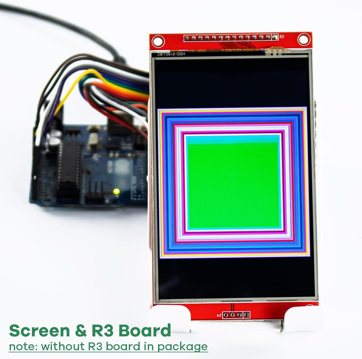
Figure 7.1: The LAFVIN 4.0-inch TFT LCD Touch Display Module connected to an Arduino R3 board (not included), showcasing a vibrant geometric pattern on the display.
7.3. SD Card Usage
The integrated SD card slot can be used to store images, fonts, or other data for your projects.
- Initialization: Initialize the SD card using `SD.begin(SD_CS_PIN)`.
- File Operations: Use standard SD library functions to read from or write to files on the SD card.
- Note: The SD card shares the SPI bus with the display. Ensure proper management of Chip Select (CS) pins to avoid conflicts. Some users report challenges with simultaneous use of SD and touch on the same SPI bus, potentially requiring a separate SPI interface for the SD card or careful pin management.
8. Maintenance
To ensure the longevity and optimal performance of your LAFVIN TFT LCD Touch Display Module, follow these maintenance guidelines:
- Cleaning: Gently wipe the screen with a soft, lint-free cloth. For stubborn smudges, use a small amount of screen cleaner designed for electronics. Avoid abrasive materials or harsh chemicals.
- Handling: Always handle the module by its edges to avoid touching the display surface or damaging components on the PCB.
- Storage: Store the module in a dry, dust-free environment, away from direct sunlight and extreme temperatures. Keep it in its original anti-static packaging if possible.
- Power: Ensure the power supply voltage is within the specified 3.3V-5V range to prevent damage.
9. Troubleshooting
This section addresses common issues you might encounter and provides potential solutions.
9.1. Display Not Working / Blank Screen
- Check Wiring: Verify all power (VCC, GND) and SPI connections (CS, DC/RS, MOSI, SCK, MISO) are correct and secure.
- Power Supply: Ensure your microcontroller is providing stable power within the 3.3V-5V range.
- Library Configuration: Double-check your display library's `User_Setup.h` file. Ensure `ST7796_DRIVER` is uncommented and pin definitions match your wiring.
- SPI Frequency: Some microcontrollers or specific display modules may have issues with very high SPI frequencies (e.g., 40MHz). Try reducing the SPI frequency in your library configuration (e.g., to 27MHz).
- Reset Pin: Ensure the RESET pin is correctly connected and toggled during initialization.
9.2. Touch Screen Not Responding
- Check Touch Wiring: Verify all touch-specific pins (T_CS, T_DIN, T_DO, T_CLK, T_IRQ) are correctly connected.
- Touch Library: Ensure the XPT2046 touch screen library is correctly installed and configured with the right pins.
- Separate SPI: The touch screen often uses a separate SPI interface or at least a distinct CS pin from the display. Ensure there are no conflicts.
- Calibration: The touch screen requires calibration. If it's responding but inaccurately, perform a calibration routine.
- Hardware Fault: In rare cases, the touch controller itself might be faulty. If all software and wiring checks fail, consider testing with another module if available.
9.3. Incorrect Colors / Display Artifacts
- RGB Order: In your display library's `User_Setup.h`, check the `TFT_RGB_ORDER` setting. It might need to be `TFT_BGR` if colors appear inverted (e.g., red is blue).
- SPI Speed: High SPI speeds can sometimes cause display artifacts. Try reducing the SPI frequency.
9.4. SD Card Not Detected / Not Working
- Check SD Card Wiring: Ensure the SD card's CS pin and shared SPI pins are correctly connected.
- SD Card Format: Ensure the SD card is formatted as FAT16 or FAT32.
- CS Pin Conflict: If the display and SD card share the same SPI bus, ensure their respective CS pins are properly managed (only one CS pin should be low at a time).
- Card Type: The module typically supports standard SD cards, not microSD directly without an adapter.
10. Warranty and Support
LAFVIN products are designed for reliability and performance. For specific warranty information or technical support, please refer to the vendor or manufacturer's official website. Keep your purchase receipt for warranty claims.


